D iffe rential inp ut, D ifferen tial in pu t, Differential inputs – Measurement Computing CIO-DAS6402/12 User Manual
Page 11
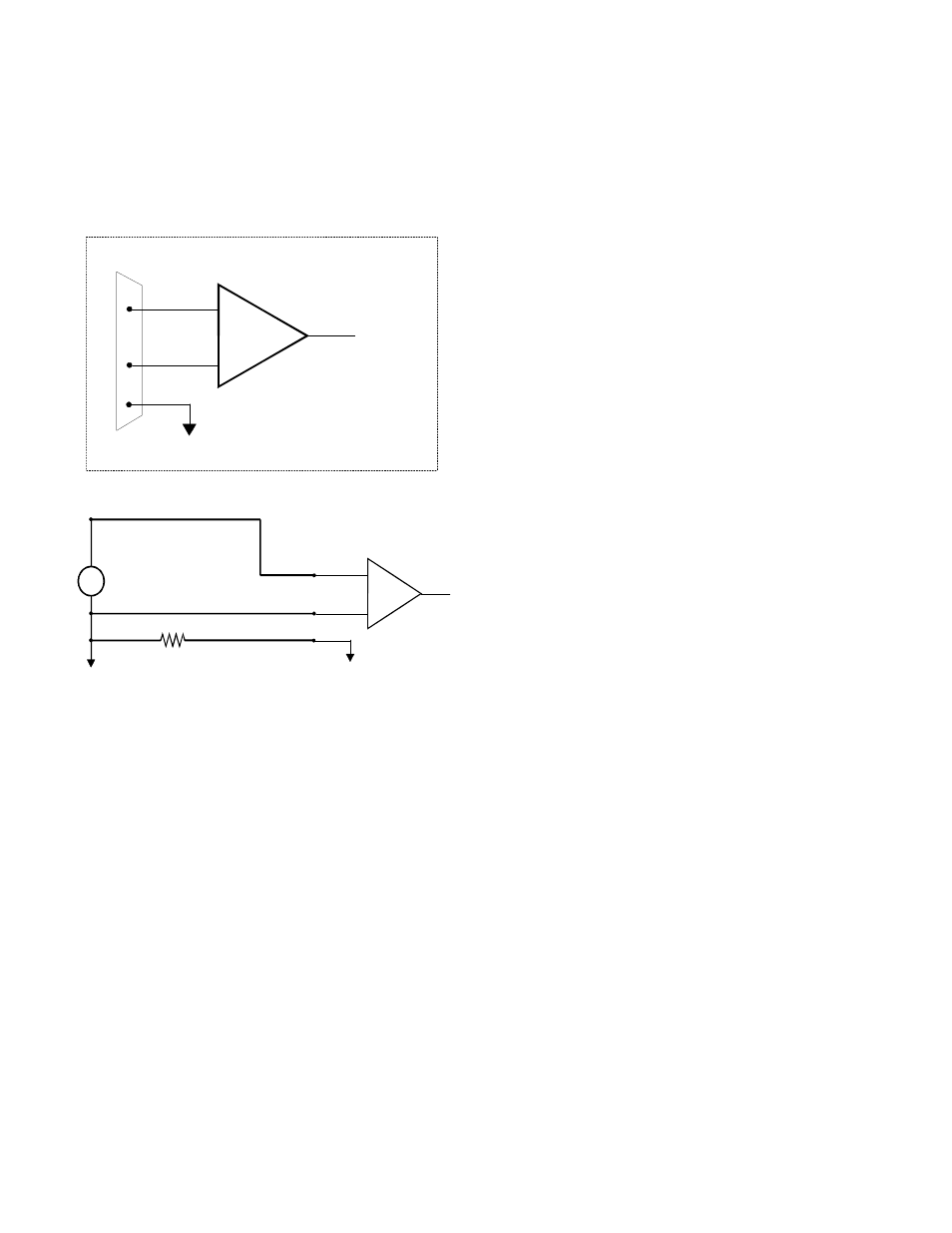
Differential Inputs
Differential inputs measure the voltage between two distinct input signals. Within a certain range (referred to as the common mode
range), the measurement is almost independent of signal source to CIO-DAS6402 ground variations. A differential input is also
much more immune to EMI than a single-ended one. Most EMI noise induced in one lead is also induced in the other, the input
only measures the difference between the two leads, and the EMI common to both is ignored. This effect is a major reason there is
twisted pair wire as the twisting assures that both wires are subject to virtually identical external influence. Figure 4-2 below shows
a typical differential input configuration.
Figure 4-2. Differential input Theory
Before moving on to the discussion of grounding and isolation, it is important to explain the concepts of common mode, and
common mode range (CM Range). Common mode voltage is depicted in the diagram above as Vcm. Though differential inputs
measure the voltage between two signals, without (almost) respect to the either signal’s voltages relative to ground, there is a limit
to how far away from ground either signal can go. Though the CIO-DAS6402 has differential inputs, it will not measure the
difference between 100V and 101V as 1 Volt (in fact the 100V would destroy the board!). This limitation or common mode range
is depicted graphically in Figure 4-3. The CIO-DAS6402 common mode range is +/- 10 Volts. Even in differential mode, no input
signal can be measured if it is more than 10V from the board’s low level ground (LLGND).
7
+
-
Inp ut
A m p
To A /D
D ifferen tial In pu t
I/O
C o nn ector
LL G N D
C H H igh
C H L ow
+
-
Inp ut
A m p
To A /D
D iffe rential
Inp ut
LL G ND
C H H igh
C H Low
~
Vs
Vs
Vcm
C om m on M ode Voltage (Vcm ) is ignored
by differential input configuration. How ever,
note that V cm + Vs m u st rem ain w ithin
the am plifier’s com m on m ode range of ±10V
Vcm = V g2 - V g1
g
g1
2