Post-installation -25, Post-installation – Hypertherm HT4400 HySpeed Plasma Arc Cutting System User Manual
Page 59
INSTALLATION
HT4400
Instruction Manual
3-25
7
Post-Installation
HT4400 Initial Startup
After installation is complete, perform the following procedure to ensure the proper performance of the
HT4400 system before moving on to the Operation section of this manual. The gas console will display error
code FS (flow switch error) on initial startup until: all air is out of the torch coolant loop; the reservoir in the
cooler has an adequate supply of coolant. Follow the procedure below to satisfy the flow switch.
1.
Verify that all installation requirements are met and that all
connections are made as outlined in this section.
2. Verify that consumables are installed properly in the torch
(see Daily Startup in the Operation section, if necessary).
3. Verify that the torch coolant has been added to the cooler
(see pages 3-3 and 3-19).
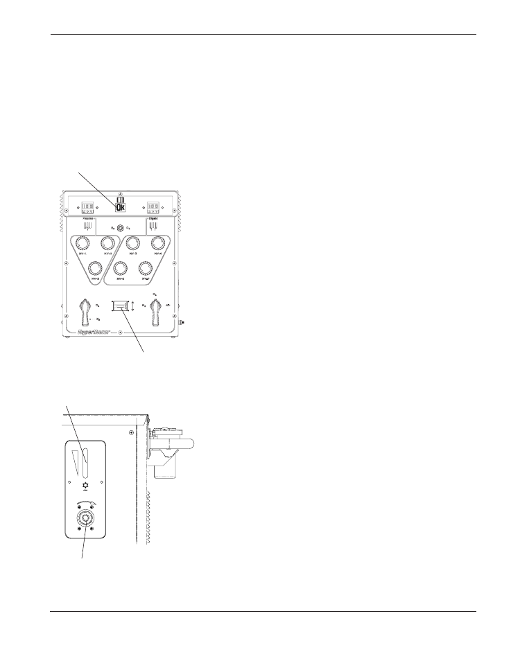
4. Position the valve select switch (S2) on the gas console to
either Leak Test 1 or Leak Test 2.
5. Switch the Control Power switch on the power supply
ON (I).
6. Allow coolant to flow through the system. If the coolant is
flowing properly, propellers on the flow switch (FS1) will be
spinning rapidly.
Note: When propellers are spinning, the individual paddles
cannot be seen.
If coolant stops flowing and FS is still displayed on the gas
console, turn valve select switch to RUN, and then back to
Leak Test 1 or Leak Test 2. This action allows the pump to
run for 30 seconds. Check coolant level.
7. After 5 minutes, switch the Control Power switch on the
power supply OFF (O).
8. Position the valve select switch (S2) on the gas console to
RUN.
9. Switch Control Power switch on the power supply ON (I).
The coolant pump should continue to run and OK should
be displayed on the gas console status display.
If FS or any other error code is displayed on the gas
console other than OK, the system has a problem that
needs to be fixed before daily operations can begin. See
the Maintenance section (Section 5) of this manual to
troubleshoot.
(under lever)
Flow switch (FS1)
propellers
Status Display
Valve Select
(S2)
Check coolant
level