Installation – rail mounted unit, Installation – curb mounted unit – Greenheck TSU Base Unit Manual (464441) User Manual
Page 4
Make-Up Air Unit
4
®
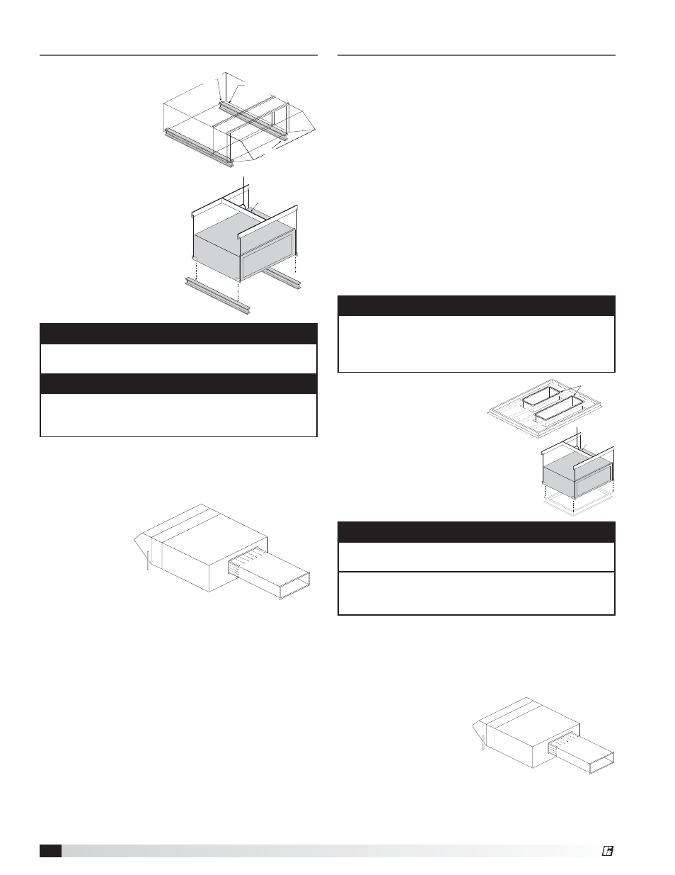
Installation – Rail Mounted Unit
1. Install Rails
Install the rails. The
rails should be located
6 to 12 inches in
from the sides of the
unit. The rails should
extend at least six
inches past the intake
and discharge ends
of the unit. Rails are
field-supplied by others
and are not supplied by
manufacturer.
2. Install Unit
Use a crane and a set of
spreader bars hooked to
the factory lifting lugs to
lift and center the unit on
the rails.
Installation – Curb Mounted Unit
1. Install Curb
Position curb on the roof (refer to the CAPS submittal
section for placement of curb in relation to the unit).
Verify that the curb is level, shim if necessary. Attach
curb to roof and flash into place.
2. Install Ductwork
If the unit has a downblast (DB) discharge, install the
supply air duct now.
If the unit requires a return air duct, install it now.
If the unit has a horizontal (HZ) discharge, wait until the
base unit is installed before installing the supply duct.
Good duct practices should be followed for all
ductwork. All ductwork should be installed in
accordance with SMACNA and AMCA guidelines,
NFPA 96 and all local codes. Refer to the CAPS
submittal for the ductwork sizes.
NOTE
The use of all lifting lugs and a set of spreader bars in
mandatory when lifting the unit.
NOTE
For easy installation, it is recommended that the
weatherhood, filter section or evaporative cooler be
installed after the base unit.
NOTE
The use of all lifting lugs and a set of spreader bars in
mandatory when lifting the unit.
For easy installation, it is recommended that the
weatherhood, filter section or evaporative cooler be
installed after the base unit.
NOTE
The use of a duct adapter is recommended on a
downblast (DB) arrangement to align the ductwork
with the supply unit and is only a guide and is not to
be used as ductwork support.
Spreader Bar
Rails extend 6 inches
from discharge end
of unit
Rails extend 6 inches
from discharge end
of unit
Rails extend
6 inches from
end of filter section
Rails extend
6 inches from
end of filter section
Rails located 6 to 12 inches
in from sides of unit.
Rails located 6 to 12 inches
in from sides of unit.
3. Attach Ductwork
Refer to the CAPS submittal for the duct size and
location. Manufacturer recommends attaching ductwork
using a rubber duct section at the unit to reduce
vibration. An
appropriate
sealant should
be used around
the discharge
opening of the
unit to create
a weathertight
seal.
Good duct practices should be followed for all
ductwork. Ductwork should be installed in accordance
with SMACNA and AMCA guidelines, NFPA 96 and any
local codes.
5. Install Ductwork
If the unit has a downblast (DB) discharge, the ductwork
should already be installed.
Refer to the CAPS submittal for the duct size and
location. Manufacturer recommends attaching ductwork
using a rubber duct section
at the unit to reduce
vibration. An appropriate
sealant should be used
around the discharge
opening of the unit to
create a weathertight seal.
Good duct practices should be followed for all
ductwork. Ductwork should be installed in accordance
with SMACNA and AMCA guidelines, NFPA 96 and any
local codes.
3. Apply Sealant
Apply an appropriate sealant
around the perimeter of the
curb and duct adapter(s) to
isolate fan vibration and prevent
water penetration.
4. Install Unit
Use a crane and a set of spreader bars
hooked to the factory lifting lugs to lift
and center the unit on the curb.
Sealant
Spreader Bar