Gasboy 1000 Series Installing Internal Modem User Manual
Page 2
C35565
7323
9.
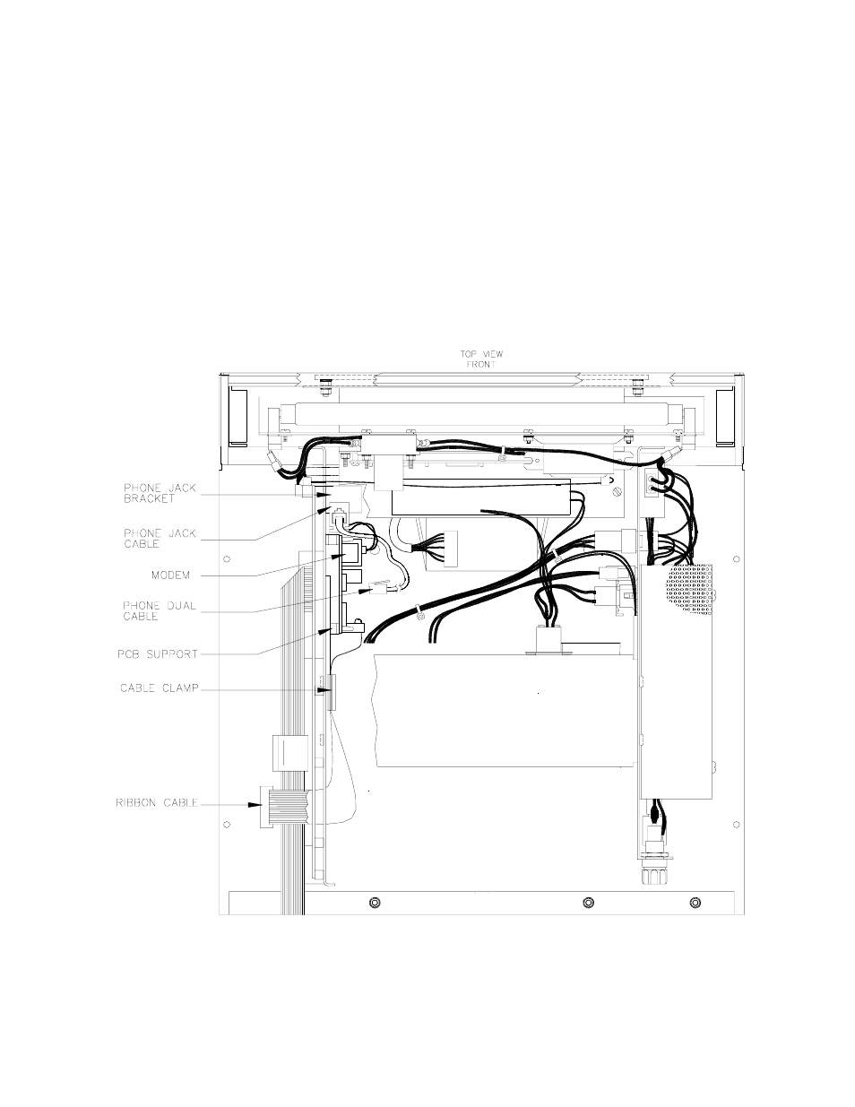
If replacing a modem, remove the old modem. Install new modem (item 7) by pressing it firmly onto the PC board
supports until they lock the modem into place. The modem must be positioned so its two connectors are on the lower
half of the modem.
10. Attach the Phone Jack Cable Assembly (item 4) to the 2-position connector of the modem so the green wire of the
cable faces down.
11. C05738 Cable: Attach this cable assembly (item 8) to the 20-position modem connector so that pin 1 (the red or dark
blue edge of the cable) faces down. Feed the other end of the cable under the MPU PCB support plate and plug it
into the J13 connector on the MPU PCB. Remove any cable that may be in the J14 or J15 connectors of the MPU
PCB.
12. Remove the backing of the Cable Clamp (item 9) and attach it to the inside of the MPU PCB support plate at a point
to the rear of the modem. It must be placed to hold the 20-position Communication Ribbon Cable Assembly out of
the way of the pump control PCBs on the rear door.
13. Attach the Phone Dual (6P/4W) Cable Assembly (item 10) from the Phone Jack Cable Assembly to the incoming
phone jack in the base of the Series 1000 pedestal. The drawing below shows current placement of all components.
14. Replace the hood of the unit and fasten it with the four external screws and two internal wing nuts removed
previously.
15. Turn on the AC power switch.
16. Close and lock the rear door of the Series 1000 head.