Gasboy 1000 Series Installing Internal Modem User Manual
Gasboy Hardware
C35565
7323
FIELD INSTALLATION OF A SERIES 1000 INTERNAL MODEM KIT
When using these instructions for replacement of a defective internal modem, disregard all steps that detail the mounting
of the modem kit hardware (4-8 and 12-13).
The Series 1000 Internal Modem Kit should contain the following parts:
Item
Qty
P/N
Description
Item
Qty
P/N
Description
1
2
C01160
Screw, 6-32 x 3/8 Pan Head Slot
7
1
C07122
Modem, internal, 2400
2
1
C34821
Bracket, Phone Jack Cable Assy.
8
1
C05738
Cable Assy., 20-pos. Ribbon Comm
3
2
039069
Nut-Hex Keps # 6-32 Plated
9
1
C02207
Clamp, Ribbon Cable
4
1
C05737
Cable Assy., Phone Jack
10
1
C05356
Cable Assy., Phone Dual (6P/4W)
5
4
C04035
Screw, SS, 6-32 x 1/4 Phillips Pan
11
1
C35565
Field Installation Instructions
6
4
C02896
Support, PC Board 3/8 Long Plastic
1.
Unlock and open the rear door of the Series 1000 head.
2.
Turn off the AC power switch located to the lower right in the rear of the head.
3.
Remove the hood of the unit from the head. This is done by removing the four external screws (two each side) which
secure the hood to the Series 1000 head. Also remove the two internal wing nuts which secure the top of the hood to
the hood support bracket.
4.
Remove the MPU PCB by disconnecting all attached cables and removing all of the screws that secure it to the MPU
PCB support plate.
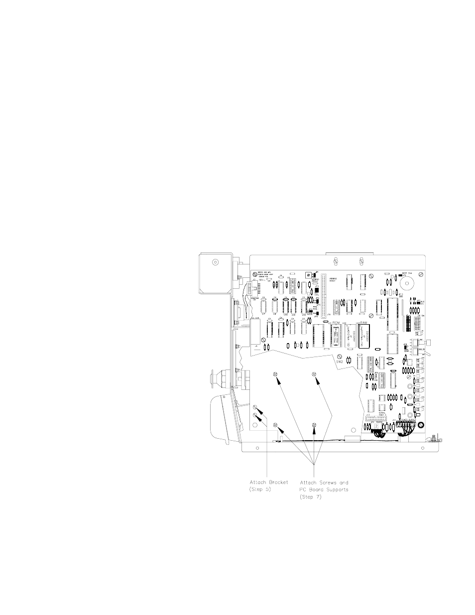
5.
Insert the 2 slotted screws (item 1),
through the two holes in the lower left
corner of the MPU PCB support plate
so the heads of the screws are facing
outward. On the inside of the plate,
slip the L-shaped bracket (item 2) over
the screws so the notch in the bracket
is facing the rear of the unit. Secure it
with the keps nuts (item 3).
6.
Install the Phone Jack Cable
Assembly (item 4) by sliding it into the
notch of the bracket so the phone jack
faces up and the wires face down.
Push the connector firmly into the
bracket notch.
7.
Insert a Phillips head screw (item 5)
through one of the four holes to the
right of the previously installed
bracket, so the head of the screw is
facing outward. Use the screw to
fasten a PC board support (item 6) to
the inside of the plate. Repeat this
procedure until all four supports are
mounted to the inside of the plate.
8.
Install the MPU PCB and secure it
with the previously removed screws.
Reconnect all cabling.