Gasboy 120VAC Fluorescent Light Kit User Manual
Page 3
C35404 Rev. 8120
Page 3
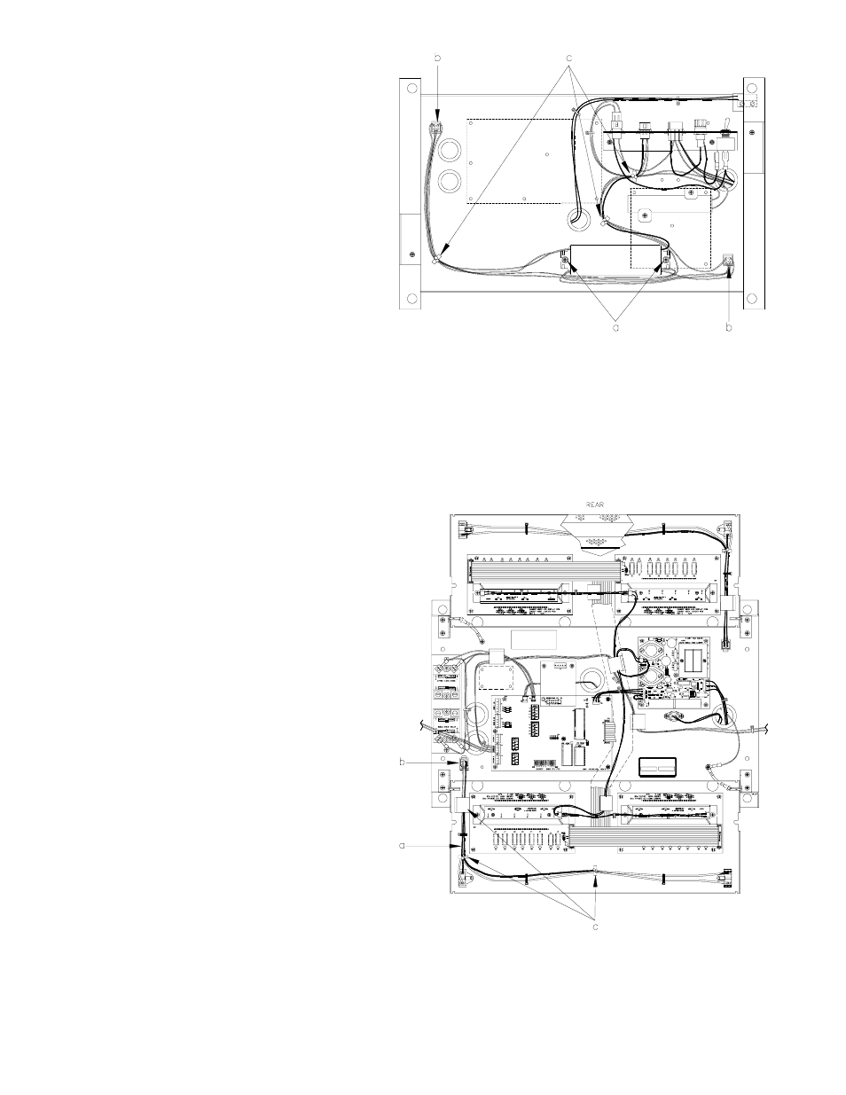
12.
On the underside of the platform, attach the
ballast assembly to the two studs using the
10-32 nuts (a) or, if no studs exist, use #8 TT
screws with Star lock washers making contact
with ballast flanges. The small #8 flat washers
slide inside the slot of both ballast flanges to
help keep the screws centered. Push the
connectors through the square holes in the
base and lock them into place (b). Install
three nylon tie wraps or wire twist standoffs to
keep the cable against the platform base (c).
13.
Place the platform assembly back into the
chassis. Push the cables up through their
appropriate bushings. Install the four nuts,
washers, and lock washers to secure the
platform to the chassis.
14.
Connect the MICRO connector to the power bracket. Locate the yellow and brown cable assembly from the AC conduit.
Connect it to the LIGHTS connector on the power bracket.
15.
Attach the AC, pulser, and handle cables to the CPU PCB. Attach the DC cable to the RS-485 PCB or Pump I/F PCB.
On relay 1, connect the red wire to screw #1 and the blue wire to screw #2. On relay 2, connect the orange wire to
screw #1 and the black wire to screw #2.
16.
Install the display panel. Attach the ribbon cables to the LCD Display PCBs and the power cables to the LED Backlight
PCBs. Attach the ground braid.
17.
Get one of the display panel light cable
assemblies. Slide the black plastic bushing
against the lamp socket with the long wires.
Standing in front of a display panel, place the
wires thorugh the notch in the right side of the
panel and snap the bushing into the hole.
Attach the lamp socket using the screws and
square nuts provided with the socket. Newer
display light cable assemblies have no black
bushing and the lamp sockets just snap into
holes in the panel (no hardware required).
The long end of the cable should wrap around
the display panel so that the wires run along
the inside of the panel. Attach the lamp
socket with the short wires to the left side of
the panel as before. The four-wire cable
should run down the left-inside of the panel
(a). Connect the cable to the ballast
connector mounted in the platform base (b).
Install five nylon tie-wraps or two wire-twist
standoffs and one stick-on cable clamp to
keep the cable against the display panel (c).
Secure the panel in the upright position.
Install the fluorescent lamp. Cover the lamp
with the perforated screen using the #8
hardware. Repeat this procedure for the other
display panel.