Gasboy 120VAC Fluorescent Light Kit User Manual
Page 2
Page 2
C35404 Rev. 8120
8.
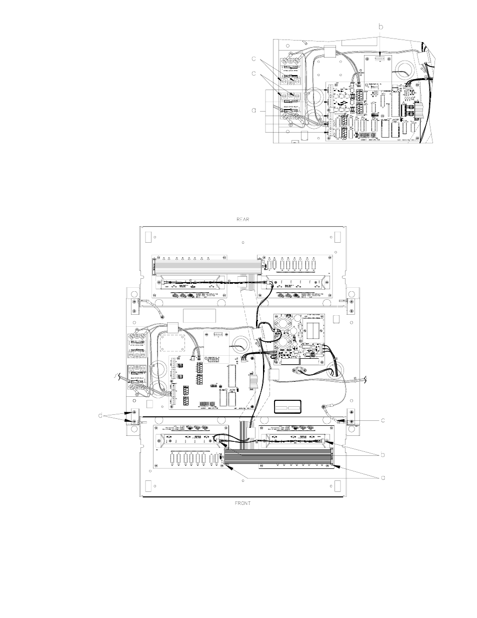
From the CPU PCB, pull off the AC, pulser, and handle
cables (a). From the RS-485 PCB or Pump I/F PCB, pull
off the DC cable (b). Disconnect the red, blue, orange,
and black wires from screws 1 and 2 of the pump relays
(c). Push all of the cables down through the platform
bushings.
9.
On one of the display panels, pull off the ribbon cables (a) from the LCD Display PCBs and the power cables (b) from
the LED Backlight PCBs. Remove one end of the ground braid cable (c) from the display panel. Remove the two
screws (d) from one of the support brackets. Be careful not to let the display panel fall while removing the support
bracket. Slide the panel away from the remaining support bracket and pull it out of the cabinet.
10.
Disconnect the MICRO connector from the power bracket.
11.
Remove the four nuts, washers, and lockwashers securing the platform assembly to the chassis. While standing on the
side with the display panel still installed, lift the platform up and out toward you.