Gasboy 9800 Single User Manual
Page 2
Page 2
C35402 Rev. 8008
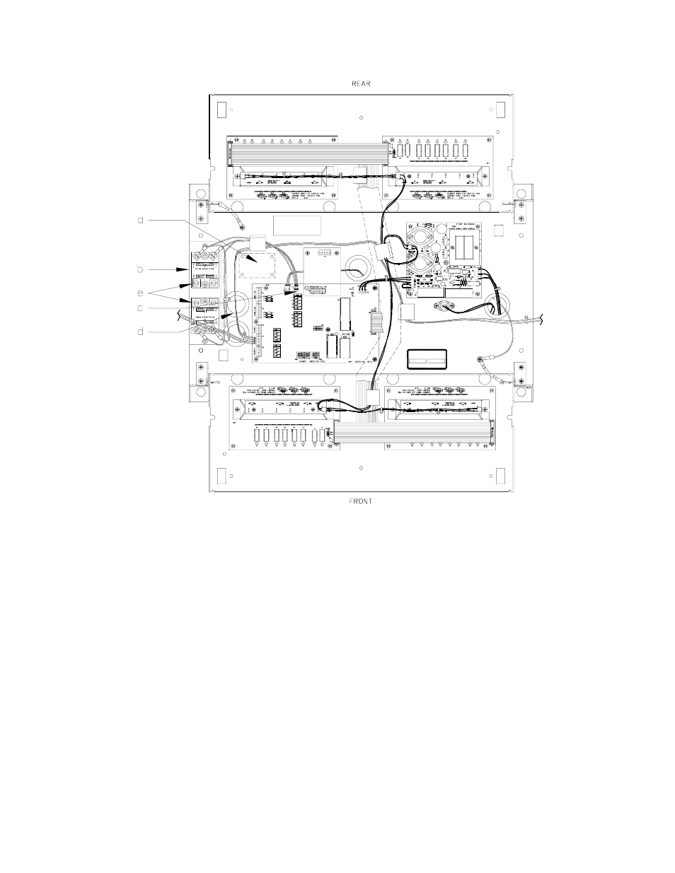
Refer to the following drawing for Steps 7 through 11.
7.
Attach the relay module to the base of the platform using the #8 hardware. (Location a for singles, b for twins.)
8.
Attach the relay cable to P7 (c) of the display CPU PCB.
9.
Locate the 14 gauge red and blue wires coming from the AC conduit under the platform. Twin dispensers will also use
14 gauge orange and black wires. Cut off the insulating terminals, strip the wire, and crimp on the spade terminals.
10. Feed the wires up through the platform bushing (d) as shown.
11. (e) Attach the red wire to screw terminal #1 and the blue wire to screw terminal #2 of relay #1. Attach the orange wire to
screw terminal #1 and the black wire to screw terminal #2 of relay #2.
12. Complete the wiring between the breaker panel, pump and AC junction box as shown in the Pump/Dispenser Installation
Manual.
13. Secure the display panel in the upright position.
14. Attach the bezel. Make sure the bezel is seated properly to insure a watertight seal.
15. Attach and lock the front panel.