Gasboy 9800 Single User Manual
Gasboy Hardware
C35402 Rev. 8008
Page 1
INSTRUCTIONS FOR SINGLE (C06484) AND TWIN (C06485) RELAY KIT
Locate and identify the following parts from the Relay Kit. Hardware and quantities may vary.
QTY PART
NO.
DESCRIPTION
1
C06681
Cable Assy., Single Relay or
C06433
Cable
Assy., Twin Relay
2
C04037
Screw, 8-32 x 3/8
2
C01171
Washer, #8 Spring Lock
2
053737
Screw, #8-32 x 3/8 TT
4
C01027
Terminal, #8 Spade (Qty. = 2 for single)
1.
Installing this kit involves wiring to the submersible pump and breaker panel. Read Sections 3 and 4 of the
Pump/Dispenser Installation Manual before proceeding.
2.
Turn off the circuit breakers supplying power to the MICRO, LIGHTS and FEED.
3.
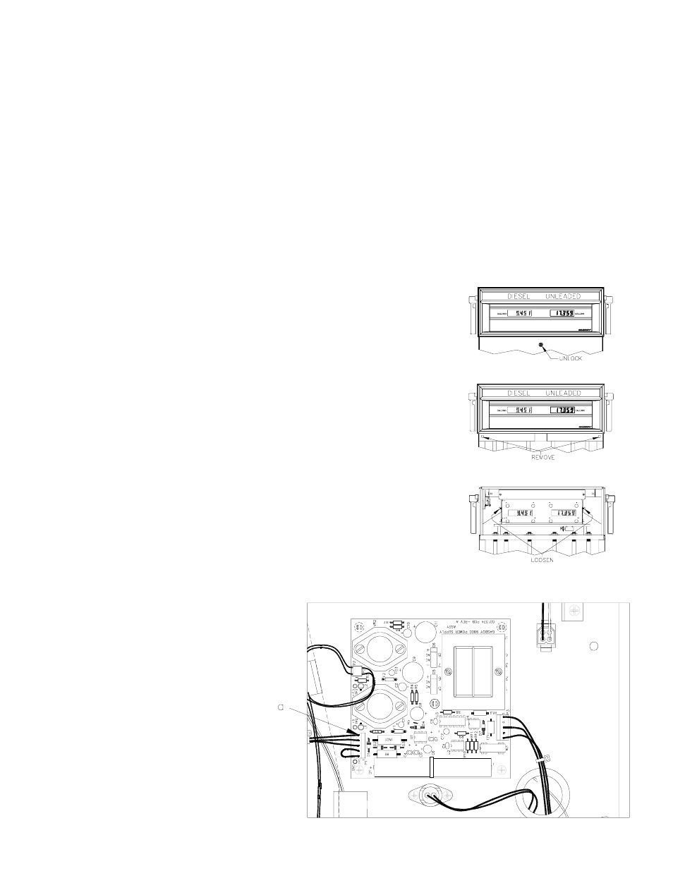
Unlock and remove the front panel.
4.
Remove the two bolts located over the tabs of the bezel assembly. Lift the bezel
assembly upwards and out to remove.
5.
Loosen, and remove if necessary, two screws located on the left and right door
support brackets and pivot the display panel down.
6.
Pull the connector off P1 (a) on the
power supply. After a few seconds,
reconnect P1.