GAI-Tronics 10959-101 Wall-Mount Audio Messenger Interface (AMI) User Manual
Page 19
Pub. 42004-398E
M
ODEL
10959-10
X
W
ALL
-M
OUNT
A
UDIO
M
ESSENGER
I
NTERFACE
P
AGE
17 of 31
f:\standard ioms - current release\42004 instr. manuals\42004-398e.doc
10/09
The Page/Party
®
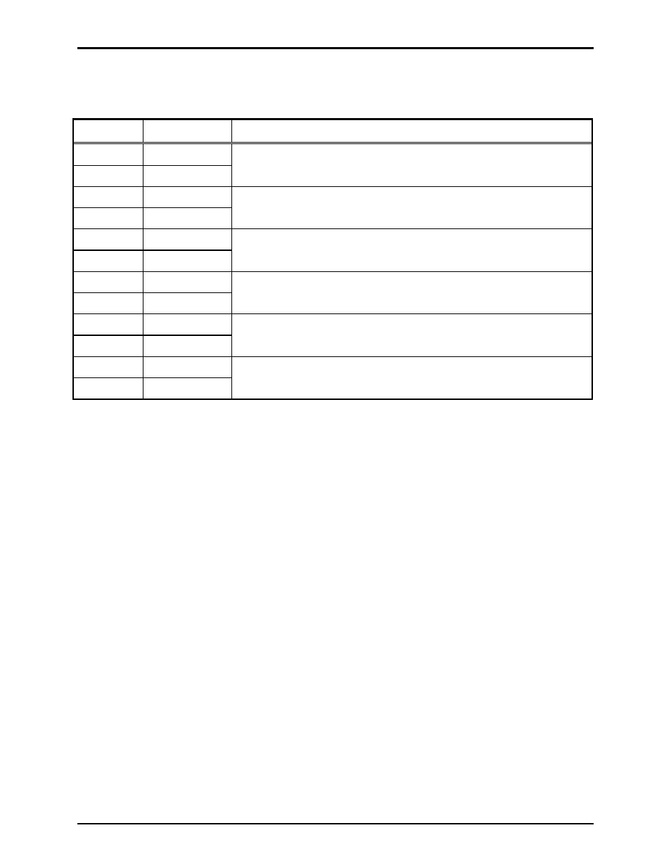
Interface TB1 terminal block assignments are as follows:
Table 9. Page/Party
®
Interface Terminal Block 1
Terminal Description Function
TB1-1 Page
(L1)
TB1-2 Page
(L2)
Connects to the page line of Page/Party
®
system.
TB1-3
Party 1 (L1)
TB1-4
Party 1 (L2)
Connects to party line 1 of the Page/Party
®
system.
TB1-5
Party 2 (L1)
TB1-6
Party 2 (L2)
Connects to party line 2 of the Page/Party
®
system.
TB1-7
Party 3 (L1)
TB1-8
Party 3 (L2)
Connects to party line 3 of the Page/Party
®
system.
TB1-9
Party 4 (L1)
TB1-10
Party 4 (L2)
Connects to party line 4 of the Page/Party
®
system.
TB1-11
Party 5 (L1)
TB1-12
Party 5 (L2)
Connects to party line 5 of the Page/Party
®
system.
Resistive line balancing is required for the page line. If the AMI is installed in an existing or new
Page/Party
®
system with a Model 305-001 Line Balance, no additional line balancing is required.
However, if no resistive line balance exists, a 33-ohm resistor must be installed in parallel with the page
line.
The 69502-xxx Page/Party
®
Interface PCBA includes the 33-ohm resistive line balancing required for
party lines. If the AMI is installed in an existing or new Page/Party
®
system with a Model 305-001 Line
Balance for each connected party line, the corresponding 33-ohm resistors in the Model 305-001 must be
removed to maintain proper audio levels.