GAI-Tronics 10959-101 Wall-Mount Audio Messenger Interface (AMI) User Manual
Page 15
Pub. 42004-398E
M
ODEL
10959-10
X
W
ALL
-M
OUNT
A
UDIO
M
ESSENGER
I
NTERFACE
P
AGE
13 of 31
f:\standard ioms - current release\42004 instr. manuals\42004-398e.doc
10/09
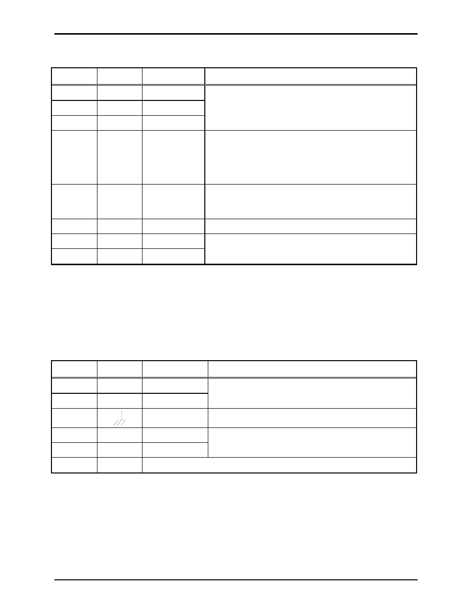
Table 5. Terminal Block 4 Assignments
Terminal Labeled Description Function
TB4-1
GND
Data (Gnd)
TB4-2
-
Data (-)
TB4-3
+
Data (+)
No customer connections
TB4-4
FLT
Fault (output)
If the AMI is operating normally, this output is active low
and can sink 100 mA maximum to external relay or
monitoring circuit. If fault is detected within the AMI, this
output switches off and stops current flow to the external
device. Refer to Figure 6 for typical connection.
TB4-5
REBOOT System reboot
When AMI is operating, this pin is 5 V dc. To reboot the
AMI, momentarily connect this pin to TB4-6.
Refer to Figure 5 for typical connection.
TB4-6
GND
Power ground
Power supply common.
TB4-7
Relay (N.O.)
TB4-8
.
Relay (com)
Solid state relay closure. On resistance = 30 ohms
When AMI is playing a message, this contact is closed.
TB5 - Auxiliary Audio
The TB5 connector (labeled
AUX)
provides connections for the following auxiliary audio inputs and a 33-
ohm page line output. Jumper P7 can be used to provide 33-ohm termination for the page line if desired.
Refer to Table 8, 69517-202 PCBA Jumper Functions, on page 14.
Table 6. Terminal Block 5 Assignments
Terminal Labeled Description Function
TB5-1
IN
Mic Input (hi)
TB5-2
COM
Mic Input (low)
Reserved for future connection for external noise-sensing
microphone.
TB5-3
Ground
Microphone cable shield termination.
TB5-4
L1
Page L1
TB5-5
L2
Page L2
Connects to the page line of the Page/Party
®
system
TB5-6
Spare