GAI-Tronics 10959-101 Wall-Mount Audio Messenger Interface (AMI) User Manual
Page 11
Pub. 42004-398E
M
ODEL
10959-10
X
W
ALL
-M
OUNT
A
UDIO
M
ESSENGER
I
NTERFACE
P
AGE
9 of 31
f:\standard ioms - current release\42004 instr. manuals\42004-398e.doc
10/09
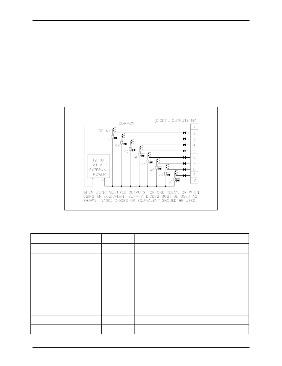
TB1 - Digital Output Connections
The TB1 connector (labeled
DIGITAL
OUTPUTS
) provides eight digital (common ground) output
connections designed to drive externally-mounted relays or other indicating circuits. Each output can
sink up to 100 mA of the current. External circuitry (relays, indicators, etc.) must be powered from an
external power supply of the same voltage used to power the AMI (12 to 24 V dc). The ground (or dc
common) terminals of the external power supply must be tied to TB1-1 and/or TB1-10. Refer to the TB1
terminal block assignment chart and Figure 2 below.
If the application includes the Model 12584-001 I/O Control Module, please refer to Pub. 42004-359 for
installation, connection and specification details.
N
OTE
: All outputs are programmed using AMI Configuration software. Each output must be
programmed before it can activate.
Table 2. Terminal Block 1 Assignments
Terminal Labeled
Function Type
TB1-1
COMMON
Ground
DC power supply common
TB1-2
AUX OUTPUT
#1
Output 1
Idle = +V dc, active (low) = sink100 mA maximum
TB1-3
AUX OUTPUT
#2
Output 2
Idle = +V dc, active (low) = sink100 mA maximum
TB1-4
AUX OUTPUT
#3
Output 3
Idle = +V dc, active (low) = sink100 mA maximum
TB1-5
AUX OUTPUT
#4
Output 4
Idle = +V dc, active (low) = sink100 mA maximum
TB1-6
AUX OUTPUT
#5
Output 5
Idle = +V dc, active (low) = sink100 mA maximum
TB1-7
AUX OUTPUT
#6
Output 6
Idle = +V dc, active (low) = sink100 mA maximum
TB1-8
AUX OUTPUT
#7
Output 7
Idle = +V dc, active (low) = sink100 mA maximum
TB1-9
AUX OUTPUT
#8
Output 8
Idle = +V dc, active (low) = sink100 mA maximum
TB1-10
COMMON
Ground
DC power supply common
Figure 2. Typical digital output relay wiring