GAI-Tronics 10959-101 Wall-Mount Audio Messenger Interface (AMI) User Manual
Page 12
Pub. 42004-398E
M
ODEL
10959-10
X
W
ALL
-M
OUNT
A
UDIO
M
ESSENGER
I
NTERFACE
P
AGE
10 of 31
f:\standard ioms - current release\42004 instr. manuals\42004-398e.doc
10/09
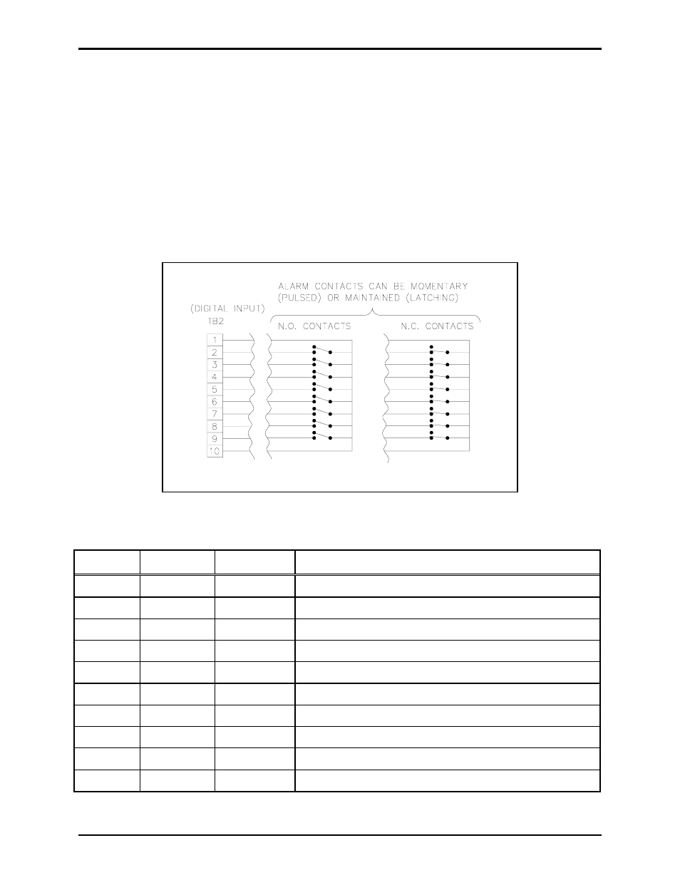
TB2 - Digital Input Connections
The TB2 connector (labeled
DIGITAL
INPUTS)
provides connection for eight contact closure inputs for
activation AMI alarms or events. Switches or relay contact closures are used to activate the AMI inputs.
The input contacts may be any combination of momentary (pulsed) switches and maintained (latched)
switches. They can be either N.O. or N.C. dry contacts rated at 5 mA or better. Inputs 1 through 8 are
programmed using the AMI Configuration Tool software.
If the application includes the Model 12584-001 I/O Control Module, please refer to Pub. 42004-359 for
installation, connection and specification details.
N
OTE
: For the inputs to operate reliably, the cable loop resistance connecting the relay/switch contact
closures cannot exceed 200 ohms. For example, using No. 24 AWG cable, the maximum cable length for
connection of the relay/switch contact closures cannot exceed 1,500 feet. Refer to the TB2 terminal block
assignment chart and Figure 3 below.
Table 3. Terminal Block 2 Assignments
Terminal
Labeled Function Type
of
Source
TB2-1
COMMON Ground
Ground reference for inputs 1 through 8
TB2-2
INPUT
#1
Input 1
Activates input #1 (as programmed)
TB2-3
INPUT
#2
Input 2
Activates input #2 (as programmed)
TB2-4
INPUT
#3
Input 3
Activates input #3 (as programmed)
TB2-5
INPUT
#4
Input 4
Activates input #4 (as programmed)
TB2-6
INPUT
#5
Input 5
Activates input #5 (as programmed)
TB2-7
INPUT
#6
Input 6
Activates input #6 (as programmed)
TB2-8
INPUT
#7
Input 7
Activates input #7 (as programmed)
TB2-9
INPUT
#8
Input 8
Activates input #8 (as programmed)
TB2-10
COMMON Ground
Ground reference for inputs 1 through 8
Figure 3. Typical input switch wiring