GAI-Tronics 10959-101 Wall-Mount Audio Messenger Interface (AMI) User Manual
Page 13
Pub. 42004-398E
M
ODEL
10959-10
X
W
ALL
-M
OUNT
A
UDIO
M
ESSENGER
I
NTERFACE
P
AGE
11 of 31
f:\standard ioms - current release\42004 instr. manuals\42004-398e.doc
10/09
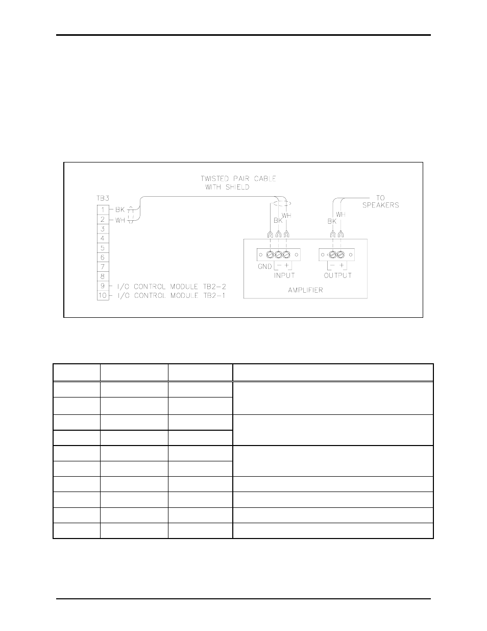
TB3 - Audio Output and Data Connections
The TB3 connector (labeled
AUDIO)
provides connections for audio inputs and outputs, and for local
RS485 data connections. Data connections are used when the AMI alarms are being controlled remotely
from a CPU or when the Model 12584-001 I/O Control Module is used to expand the inputs and outputs
to 40 each. A 600-ohm balanced audio output is provided to drive a power amplifier. Refer to the TB3
terminal block assignment chart and Figure 4 below.
N
OTE
: If only 600-ohm audio will be used, ensure that jumper P7 is installed in position 1-2 to properly
terminate the 33-ohm output. Refer to Table 8, 69517-202 PCBA Jumper Functions, on page 14.
Table 4. Terminal Block 3 Assignments
Terminal Labeled
Description Function
TB3-1
LINE
-
Page (L1)
TB3-2
LINE
+
Page (L2)
Audio output (line level) to public address amplifier.
Refer to Figure 4.
TB3-3
L1
Audio 2 (L1)
TB3-4
L2
Audio 2 (L2)
No customer connections – used for internal
connections to Telephone Interface PCBA
TB3-5
L1
Audio 1 (L1)
TB3-6
L2
Audio 1 (L2)
No customer connections – used for internal
connection to Telephone Interface PCBA.
TB3-7
POWER
GND
Power ground
Power supply common
TB3-8
DATA
GND
Data ground
N/C
TB3-9
DATA-
Data (-)
To Model 12584-001 I/O Control Module (TB2-2)
TB3-10
DATA+
Data (+)
To Model 12584-001 I/O Control Module (TB2-1)
Figure 4. Typical amplifier input wiring