GAI-Tronics 10959-101 Wall-Mount Audio Messenger Interface (AMI) User Manual
Page 16
Pub. 42004-398E
M
ODEL
10959-10
X
W
ALL
-M
OUNT
A
UDIO
M
ESSENGER
I
NTERFACE
P
AGE
14 of 31
f:\standard ioms - current release\42004 instr. manuals\42004-398e.doc
10/09
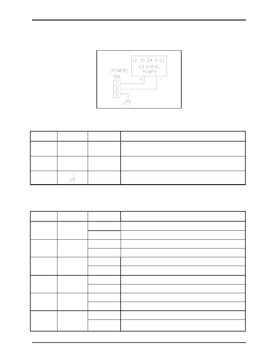
TB6 - Power Connections
The AMI requires a dc power supply. The dc power supply voltage must be between 12 and 24 V dc.
TB6 is used for power connections. Please refer to Figure 7 and Table 7 below.
Figure 7. Power connections at TB6
Table 7. Terminal Block 6 Assignments
Terminal Labeled
Description
Function
TB6-1
+
Power (+)
12 to 24 V dc power supply positive terminal
(Black wire with white stripe from power supply)
TB6-2
-
Power (-)
12 to 24 V dc power supply negative terminal
(Solid black wire from power supply)
TB6-3
Ground Earth
ground
69517-202 Jumper Settings
Table 8. 69517-202 PCBA Jumper Functions
Jumper Output
Position Function
1-2
600-ohm termination resistor connected
P1 TB3-5,
6
Audio bus 1
2-3
Default - unterminated
1-2
600-ohm termination resistor connected
P5 TB3-1,
2
600 ohms
2-3
Default - unterminated
1-2
600-ohm termination resistor connected
P6 TB3-3,
4
Audio bus 2
2-3
Default - unterminated
1-2
33-ohm termination resistor connected
P7 TB5-4,
5
33 ohms
2-3
Default - unterminated
1-2
33-ohm page output always active
P9 TB5-4,
5
33 ohms
2-3
Default – 33-ohm page output active with audio
1-2
Supervision resistor network, 4.7k in series, 15k in parallel
P11 TB4-7,
8
Audio
contact
2-3
Default - unsupervised