On board debug led code table – Foxconn N68S7AA-8EKRS2H User Manual
Page 85
Appendix
77
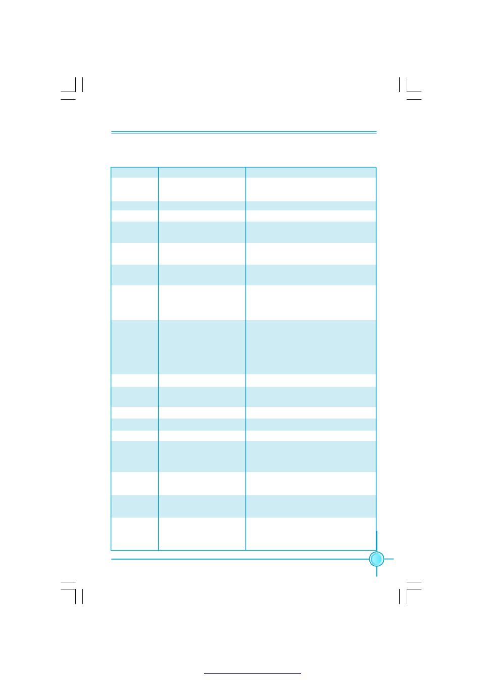
On board Debug LED Code Table
Code(hex)
Name
Description
D0
Init at power on
Initialize Bootblock and CPU at power
on.
D1
Enable IO Devices
Enable SIO devices for BootBlock.
D2
Verify BB Checksum
Verifies the integrity of BootBlock code.
D3
Init At Early BB
Prepares the system for memory
detection and sizing.
D4
Memory sizing
Performs base memory test. If base
memory test fails,system hangs.
D5
Copy BB To RAM
Copy the BootBlock to RAM and
transfers control to RAM.
D6
Check For Recovery
Checks if there is a BootBlock recovery
request either by
CMOS Setup Question.
D7
Give Control To Int
Find the Interface module in the BIOS
image(in RAM) and copies to lower
memory where it will reside through
POST. control goes to Interface
module to continue with POST.
D8
Decompress main BIOS Decompress the complete BIOS code.
D9
Copy BIOS Segs
Copy all the BIOS segments to its final
destination.
DA
Execute POST Kernel
Execute BIOS POST.
01
Reserved
02
Reserved
03
Init at early POST
Initialize BIOS, POST, Runtime data
area, BIOS modules on POST entry and
GPNV area.and Initialized CMOS.
04
Init cmos
Verify if CMOS checksum is OK or not
and do initialize correspondingly.
05
Init Interrupt
Initializes the interrupt controlling
hardware and interrupt vector table.
06
Init system timer
Initialize CH-0 as system timer. Install
the POSTINT1Ch handler. Enable
IRQ-0 in PIC for system timer interrupt.
PDF 文件使用 "pdfFactory" 试用版本创建