Chapter 2 installation instructions – Foxconn N68S7AA-8EKRS2H User Manual
Page 22
Chapter 2 Installation Instructions
14
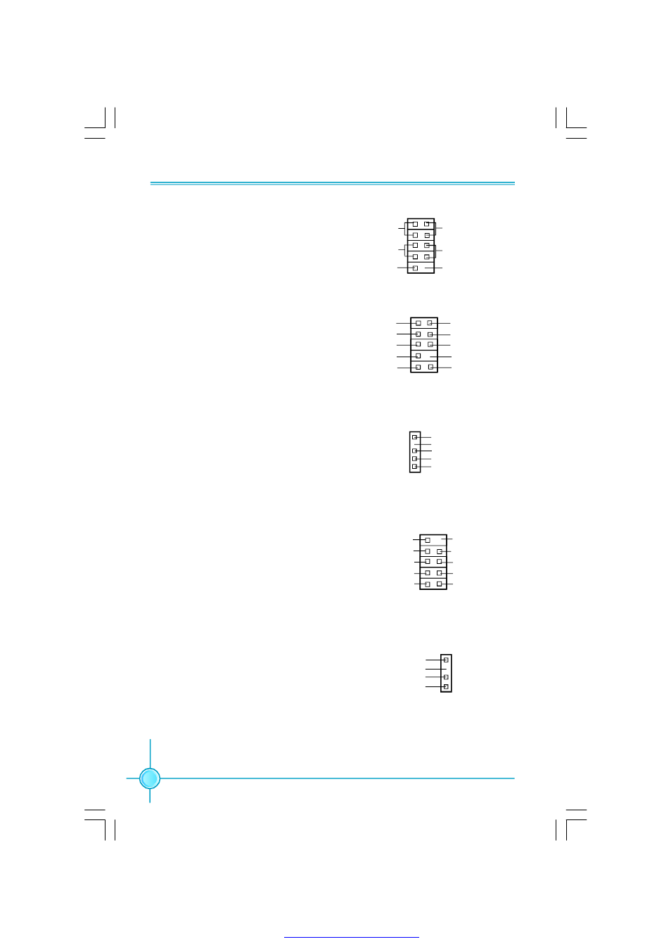
Audio Connector: F_AUDIO
The audio connector supports HD au-
dio standard. It provides two kinds of au-
dio output choices: the Front Audio, the
Rear Audio. Front Audio supports re-task-
ing function.
IrDA Connector: IR
This header supports wireless transmit-
ting and receiving device. Before using
this function, configure the settings of
IR Mode from the “Advanced BIOS
Fetures” section of the CMOS Setup.
1394 Connector:
F_1394
The 1394 expansion cable can be con-
nected to either the front (provided that
the fro n t p an el o f yo ur ch assis is
e q u i p p e d w i t h t h e a p p r o p r ia t e
interface) or real panel of the chassis.
S/PDIF Out Connector: SPDIF_OUT
The SPDIF OUT connector is capable of
provid in g digital au dio to external
speaker or compressed AC3 data to an
external Dolby digital decoder.
Power Switch Connector (PWRSW)
Attach the connector to the power button
of the case. Pushing this switch allows
the system to be turned on and off rather
than using the power supply button.
IR
1
+5V
GND
IRRX
IRTX
Empty
SPDIF_OUT
1
SPDIF_OUT
+5V
GND
Empty
NC
HDD-LED
RESET-SW
PW R-LED
PWR-SW
9
10
1
2
FP
FP1
!
+
-
+
-
Empty
1
F_AUDIO
PORT2_L
SENSE_SEND
PORT1_L
PORT1_R
PORT2_R
AUD_GND
PRESENCE_J
SENSE1_RETURN
SENSE2_RETURN
Empty
1
2
GND
+12V
TPB -
GND
TPA -
+12V
TPB +
GND
TPA +
Empty
F_1394
9
10
PDF 文件使用 "pdfFactory" 试用版本创建