Foxconn N68S7AA-8EKRS2H User Manual
Page 16
Chapter 2 Installation Instructions
8
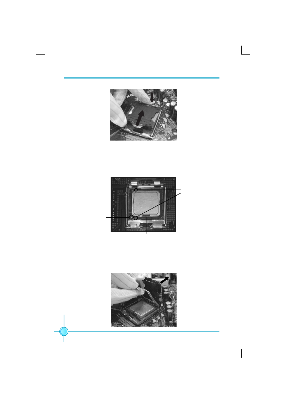
3. Hold CPU with thumb and forefinger. Ensure fingers align to socket cutouts.
Match the CPU triangle marker to Pin 1 position as shown below. The alignment
key also provides the orientation directed function. Lower the CPU straight down
without tilting or sliding the CPU in the socket.
4. After installing the CPU, remove the protective cover from load plate. The
protective cover is used to protect the contacts of the socket. Do not discard the
protective cover. Always replace the socket cover if the CPU is removed from the
socket.
A lig n m e n t
Key
Socket
Cutouts
Pin 1
position
PDF 文件使用 "pdfFactory" 试用版本创建
See also other documents in the category Foxconn Motherboard:
- AHD1S-V (42 pages)
- 865PE7MF-SH (63 pages)
- 945P7AA-8EKRS2H (119 pages)
- 661FX7MF-S (64 pages)
- K7S741GXMG-6L (10 pages)
- 748K7AA-ERS (10 pages)
- NF3250GK8AA-EKRS (68 pages)
- 6100M2MA-RS2H (94 pages)
- NF4K8AB-RS (75 pages)
- K8S755M-6LRS (104 pages)
- 6497MB-S (107 pages)
- 945P7AA-8EKRS2H (106 pages)
- 755FXK8AA-ERS (108 pages)
- 760GXK8MC-RSH RAID (45 pages)
- 760GXK8MC-RSH (75 pages)
- 761GXK8MC-RSH (85 pages)
- CK804K8MA-KS (55 pages)
- NF3UK8MA-RS (70 pages)
- NF4XK8MC-RSH (68 pages)
- NFPIK8AA-8EKRS (110 pages)
- 761GXK8MB-RSH (87 pages)
- K8M890M2MA-RS2H (69 pages)
- K8T890M2AA-RS2H (62 pages)
- MCP61VM2MA-RS2HV (61 pages)
- N5VM2AA-KRS2H (2 pages)
- N570SM2AA-8EKRS2H (87 pages)
- C51XEM2AA-8EKRS2H (114 pages)
- 761MX (44 pages)
- 761GXM2MA-RS2 (65 pages)
- A6VMX (44 pages)
- A74ML Series (105 pages)
- A7VML Series (105 pages)
- A85GM (104 pages)
- A7VA-S (106 pages)
- A7VA-S (107 pages)
- M61PMP-K (111 pages)
- A7DA-S 3.0 (112 pages)
- A9DA-S (115 pages)
- Cinema II Premium (114 pages)
- A7VMX Series (106 pages)
- 720MX-K (112 pages)
- 720AL (110 pages)
- A79A-S (115 pages)
- 560A (46 pages)
- M61PMX (92 pages)