Flowserve DMX User Manual
Page 41
DMX/DMXD/DMXH/DMXDH USER INSTRUCTIONS ENGLISH 85392728 - 10/09
Page 41 of 60
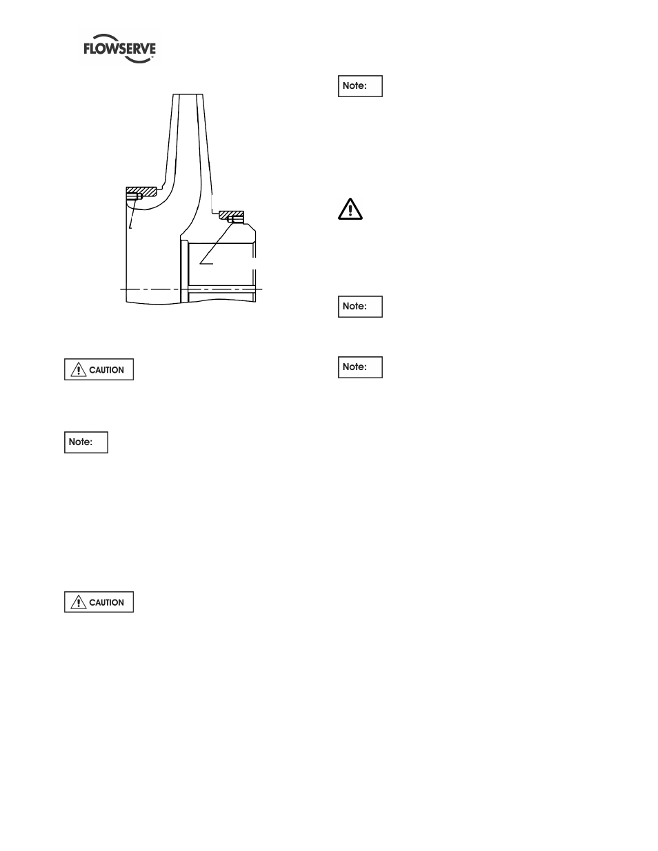
Typical axial screw installation for impeller rings.
6.8.4
Rebuilding rotor
Before upstaging or destaging a pump
(adding or removing impellers), contact Flowserve
Customer Service department for instructions, to
avoid permanent damage to the pump rotor.
Split rings and keys shall be pre-fitted and
marked for proper location before assembling rotor.
Impellers shall be marked for proper location prior to
heating for assembling on rotor.
a) Install center stage impeller key [6700], into key
way in shaft and pre-fit split rings [2531] to shaft.
Split rings to fit snug in groove.
b) All impeller bores and shaft outside diameters are
to be dimensionally inspected.
Impeller-to-shaft fit must be minimum
of 0.0254 mm (0.001in.) to 0.0762 mm (0.003 in.)
interference fit.
c) Heat the center impeller [2200] in the suction
side in oven, and assemble to shaft, moving the
impeller past the split ring groove in the shaft.
Quickly install split ring [2531] and pull impeller
back to seat against split ring. Constant heat
source is preferred to torch; torch is not
recommended.
Make sure impellers are installed for proper
rotation and location.
d) Install center sleeve [2450] from the opposite end
of shaft. Center sleeve is to be seated against the
impeller hub installed in Step c).
e) Place casing ring [1500] on impeller front ring.
Put the case ring on the previous impeller
before assembling the next impeller. Failure to do
so will require a complete dismantle of the rotor.
f) Continue to assemble remaining inboard
impellers [2200] per steps a), c) and e).
In case of double suction pump (DMXD and
DMXDH), install crossover sleeve [2450] before
assembling the first stage impeller.
Let entire rotor cool after removing several
components with heat as there may be a build-up of
heat in the rotor. It's recommended that runout of
shaft be checked.
g) Assemble outboard impellers [2200] per steps a),
c) and e).
h) Install throttling sleeve key [6700] to shaft and
pre-fit split rings [2531] in shaft to fit smug in
groove. Heat the throttling sleeve and slide onto
shaft far enough to expose split ring groove.
Install split ring and pull sleeve back to seat
against split ring.
6.8.5
Indicate and dynamic balance rotor
a) Place the rotor assembly on "V" blocks or rollers.
The runout of all impeller wear rings and
bushings is not to exceed 0.05 mm (0.002 in.)
TIR.
b) All pump rotors are to be dynamic balanced.
Refer to 6.7.2 section for grinding for balance
information.
6.8.6
Installing rotor in casing
a) The seal chamber bushing [4132], throttle
bushing [1630], channel rings [1500] and center
bushing [1600] should be checked to make sure
they seat in both the upper and lower half casing
and that the anti-rotating pins [2923] can be
IMPELLER
IMPELLER RING
SET
SCREW
SET SCREW
IMPELLER RING