6 disassembly – Flowserve DMX User Manual
Page 36
DMX/DMXD/DMXH/DMXDH USER INSTRUCTIONS ENGLISH 85392728 - 10/09
Page 36 of 60
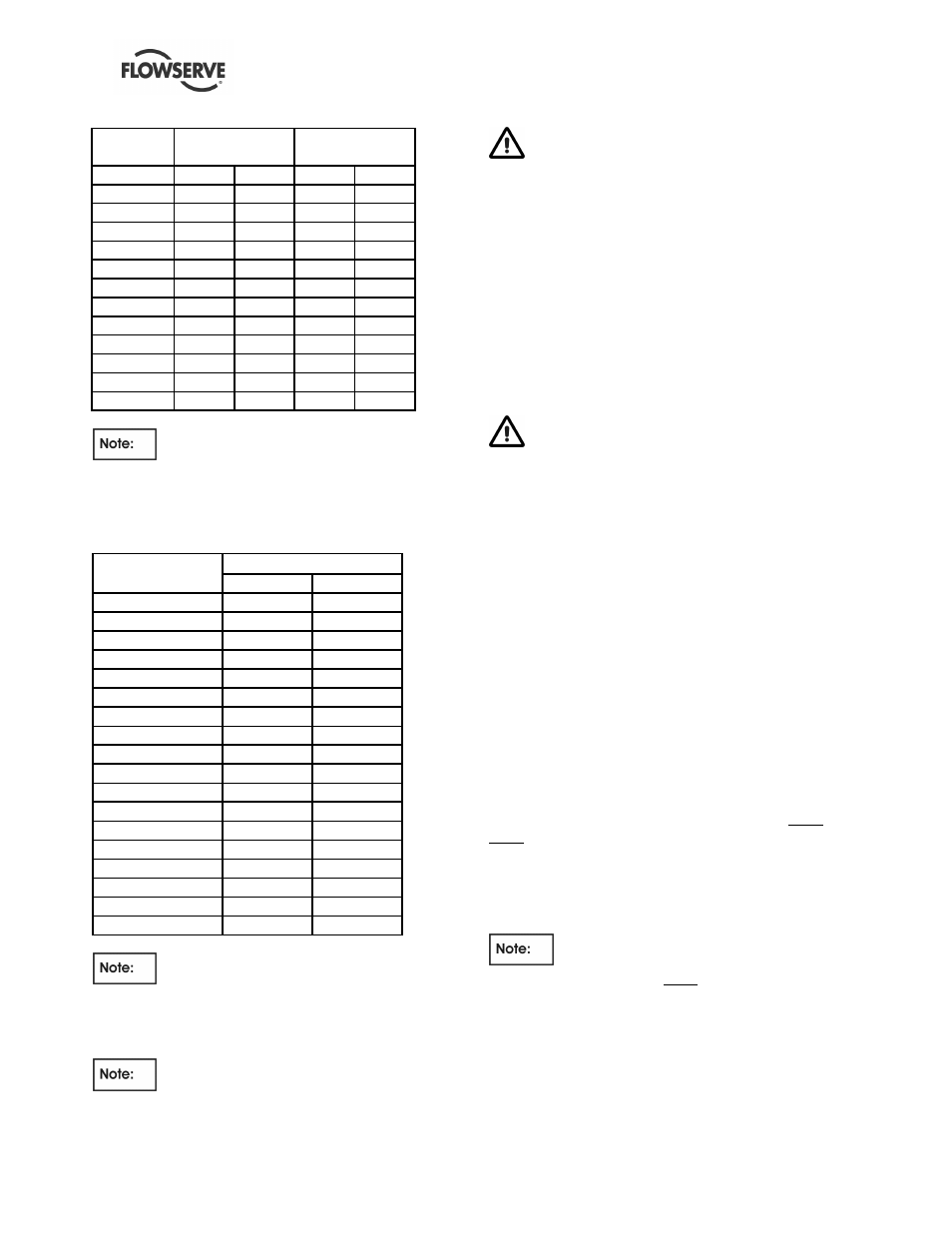
STUD SIZE
DMX/DMXD
PUMP
DMXH/DMXDH
PUMP
INCH UN 8
Nm
lbf ft
Nm
lbf ft
1.125
750
550
930
685
1.250
1050
775
1310
965
1.375
1425
1050
1775
1310
1.500
1700
1250
2100
1550
1.625
2300
1700
2875
2120
1.750
3150
2320
3930
2900
1.875
4200
3100
5220
3850
2.000
4600
3400
5760
4250
2.250
6670
4920
8340
6150
2.500
9220
6800
11525
8500
2.750
12420
9160
15525
11450
3.000
16160
11920
20200
14900
The above torque values will be applied
only when the casing hydro test pressure is equal to
or less than the values showing in the following table.
Any hydro test pressure exceeding these values must
have torque values cleared by Flowserve.
PUMP TYPE
MAX. HYDRO PRESSURE
bar
psi
3x8DMX
207
3000
3x10DMX
276
4000
3x10DMXH
414
6000
4x10DMX/DMXD
276
4000
4x10DMXH/DMXDH
414
6000
4x11DMX/DMXD
276
4000
4x11DMXH/DMXDH
414
6000
6x11DMX/DMXD
276
4000
6x11DMXH/DMXDH
379
5500
6x13DMX/DMXD
224
3250
6x13DMXH/DMXDH
345
5000
8x13DMX/DMXD
224
3250
8x13DMXH/DMXDH
248
3600
8x14DMX/DMXD
224
3250
8x14DMXH/DMXDH
248
3600
8x15DMX/DMXD
207
3000
8x15DMXH/DMXDH
248
3600
10x16DMXD
186
2700
The above torque values apply only to
standard stud material, i.e. ASTM A193 GrB7. Any
other material must have torque values cleared by
FLOWSERVE.
The above torque values assume good
thread well greased.
When reassembling the pump, all fasteners
must be tightened to the correct torque value.
Failure to observe this warning could result in
injury to operating personnel.
6.6 Disassembly
For a better understanding of this section please refer
to the exploded views drawings in section 8.
6.6.1
Dismantling procedure
a) Remove all auxiliary piping and instrumentation
that will interfere with disassembly, and drain oil
from bearing housings.
Use extreme caution not to expose
maintenance personnel to hot liquids when
removing auxiliary piping or draining bearing
housings.
b) Remove temperature detectors (if supplied) and
all other instruments from bearing housings.
c) When mechanical seals are used, loosen piping
and seal gland bolting.
6.6.2
Removal of seal chamber parts
To remove mechanical seal from pump:
a) Install setting plates/eccentric washer in place.
b) Loosen drive collar.
c) Remove gland bolting.
d) Slide mechanical seal from shaft after bearing
housings are removed as described in 6.6.4 and
6.6.5.
Seal may be disassembled/inspected/reassembled
per seal manufacturer’s drawing and instructions in
Appendix of this manual.
After reassembly of seal, setting
plates/eccentric washers must be removed before
start-up.
6.6.3
Coupling removal
Remove coupling guard. Remove coupling bolting
and remove the spacer piece (if used). Loosen set-
screws in coupling nut and remove nut.