Flowserve DMX User Manual
Page 40
DMX/DMXD/DMXH/DMXDH USER INSTRUCTIONS ENGLISH 85392728 - 10/09
Page 40 of 60
Grinding must not be performed in the area within
19mm (¾") of the final diameter of the impeller.
Grinded area’s shall have a smooth transition to the
not grinded areas and shall be polished. Minimum
thickness of impeller shrouds after balancing may not
be less than 80% of the nominal thickness per detail
drawing.
6.8 Assembly of pump and seal
When reassembling pump, all fasteners must be
tightened to the proper torque values. Refer to
sectional drawing in section 8.
6.8.1
Bearing handling information
Bearings require proper handling and installation to
ensure optimum performance. The following
information is intended as a minimum to ensure that
the bearings are handled and installed properly.
a) Do not remove new bearings from their storage
package except to inspect the bearings, when
stored for a long period of time or just prior to
their installation.
b) Work area must be clean to ensure that no dirt or
other contaminates will enter the bearings.
Handle bearings with clean, dry hands and with
clean, lint free rags. Lay bearing on clean paper
and keep covered. Never expose bearings on a
dirty bench or floor.
c) Do not wash a new bearing. It is already clean
and the preservative should not be removed.
d) Before mounting, be sure shaft bearings areas
are clean and free of nicks and burrs. Check the
dimensions of these areas to ensure correct fit of
bearings.
Under no circumstances are the bearings to
be left exposed; they should be protected by
wrapping or covered.
6.8.2
Bearing installation
a) When bearings are installed on shaft or journal
sleeve, make sure bearing is installed squarely
and is firmly seated. Hold bearing in place until it
has cooled sufficiently so that it will not move
from position. Cover bearings to protect them
from dirt.
b) When installing bearing housing onto the bearing
and shaft, the bearing housing bores and bearing
outside diameter should be coated with the
grease or lubricating oil to facilitate assembly.
6.8.3
Impeller ring installation
Impellers ring setscrews can be either axial or radial
through the hub.
Make sure ring fit on impeller is free of nicks and
burrs. Install the set-screws in the tapered holes on
the ring fits. Radial set screw shall be installed in
such a way that the socket end is accessible from the
inside of the impeller and the point end is just slightly
below the ring fit land. It may be easier to install the
radial set screw from the outside of the impeller.
Heat the new ring to 148
°
C. (300
°
F.) in convection
oven to allow for uniform heating. Do not use a torch
as this may cause local re-tempering of the material.
After the rings are thoroughly heated, they can be
assembled on the impeller hubs. Only one of the
internal edges has been machined with a lead in
chamfer. Radial location is unimportant as the
uniform cross-section around the circumference. Ring
must fit up against the shoulder provided on hubs for
proper assembly.
After cooling tighten all the set-screws with an allen
wrench.
Rings were machined to final size. They do not have
to be turned after assembly.
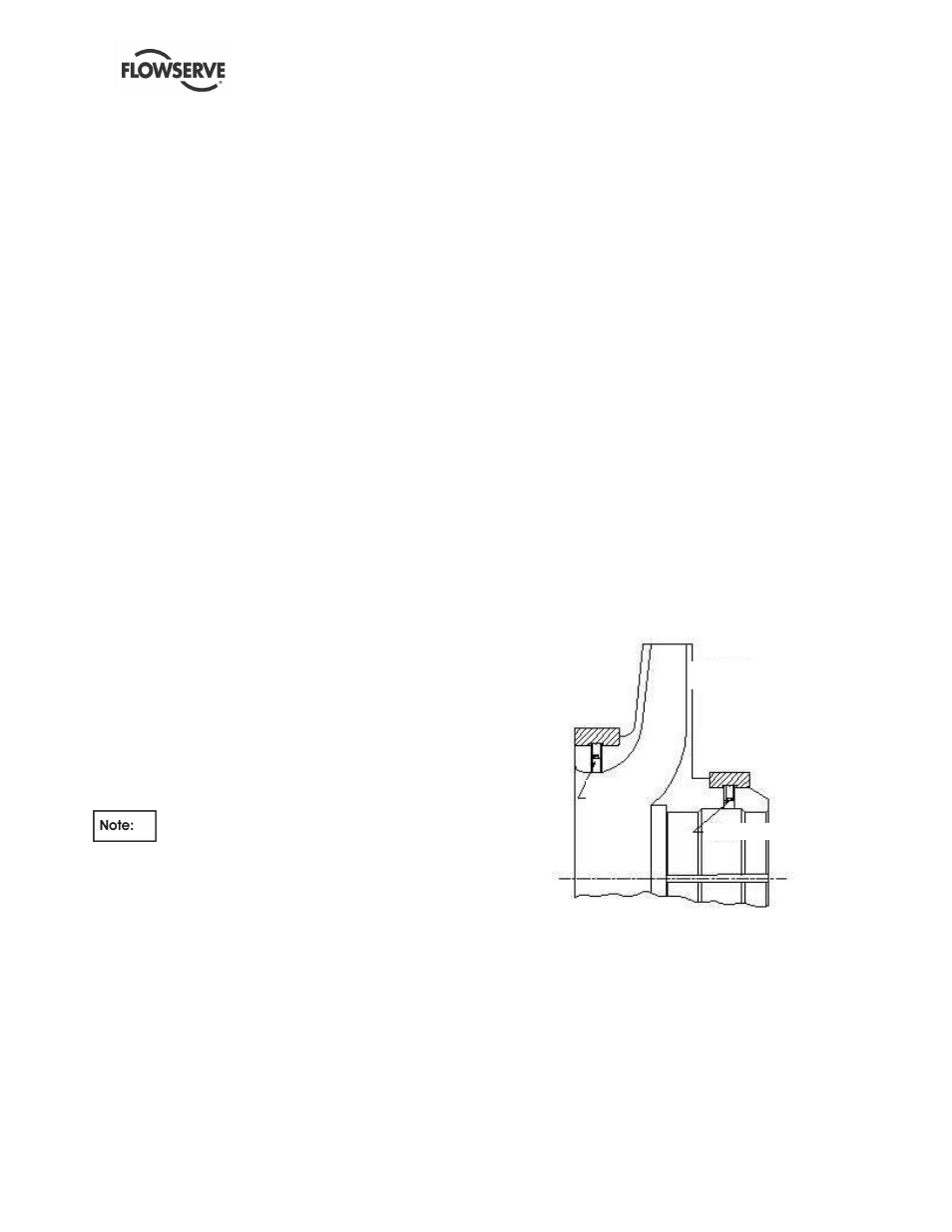
Typical radial screw installation for impeller rings.
IMPELLER RING
SET SCREW
SET
SCREW
IMPELLER
IMPELLER RING