Flowserve DMX User Manual
Page 39
DMX/DMXD/DMXH/DMXDH USER INSTRUCTIONS ENGLISH 85392728 - 10/09
Page 39 of 60
g) Repeat Steps c) and d) until all impellers are
removed on the outboard impellers.
Let entire rotor cool after removing several
components with heat as there may be a build-up of
heat in the rotor.
h) Heat must be applied to remove center sleeve
[2450].
i)
Continue to disassemble the impellers by
repeating steps c) and d) until all impellers [2200]
have been removed from the shaft.
In case of double suction pump (DMXD and
DMXDH), remove crossover sleeve [2450] after the
first stage impeller is removed by applying heat.
6.6.9
Impeller ring removal
Remove impeller rings by removing the set-screws
[6570] and machine off.
6.6.10 Parting flange gasket
Remove all traces of old gasket [4590] material.
When using any tool to surfaces remove gasket
material, do not gouge machined surfaces. Do not
reuse the gasket once the casing is opened. Use only
Flowserve recommended replacement materials.
6.7 Examination of parts
6.7.1
Inspection and renewal of parts
a) Having completely dismantled the rotor, check
the shaft for runout using "V" blocks or rollers
placed under the normal running areas. Runout
not to exceed 0.050 mm (0.002 in.) TIR.
b) Wire-brush the pump parts thoroughly. Clean off
all scale, carbon etc. Examine parts for wearing
corrosion and erosion.
c) Check throttling sleeve, center sleeve and
crossover sleeve (if supplied) for wear. Replace if
required.
d) The casing ring/impeller rings are renewable and
should be replaced when badly grooved, and/or
when the pump performance does not meet the
system requirements. Whenever it becomes
necessary to replace either wearing ring, both
rings involved (casing ring and impeller ring)
must be ordered and replaced as they are
furnished standard size only.
If new casing rings are used, make sure that they
seat in both the upper and lower half casing and
that the anti-rotation device is properly located in
its respective lower half casing fit. The use of a
scraper on the ring to casing fit will help to fit the
ring to the casing.
e) Using a torch could change the metallurgy of the
rings if too much heat is applied. Removing
impellers with torch is acceptable but putting on
new impeller rings shall be done with oven
instead of torch.
6.7.2
Dynamic-balance impeller
Whenever an impeller is tampered with, (i.e. new
impeller, wear rings installed etc.) the impeller must
be dynamically balanced before being reassembled
to shaft.
Dynamic balance shall be performed on a suitable
balancing machine by trained personnel.
Two balance planes shall be used and located
equidistance as possible from the center of gravity of
the impeller.
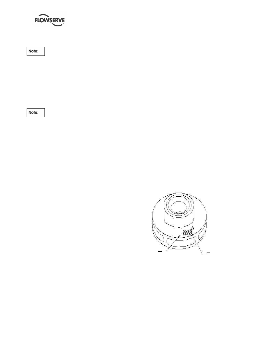
Metal shall be removed from the impeller shrouds
during the balancing operation in accordance with the
attached sketches until the impeller is within
acceptable tolerance limit of unbalance.
Grinding impeller for dynamic-balance
The maximum allowable unbalance at each of the
two planes shall be calculated as follows:
U =4 W / N or .01 oz-in whichever is greater.
U = Unbalance per plane oz-in
W = Impeller weight per plane lb.
Usually 1/2 the total impeller weight.
N = Operational rotational speed RPM
POINT OF
UNBALANCE
GROUND
AREA