Flowserve DMX User Manual
Page 38
DMX/DMXD/DMXH/DMXDH USER INSTRUCTIONS ENGLISH 85392728 - 10/09
Page 38 of 60
bushing [1600] if double suction design (DMXD and
DMXDH) will be removed with rotor.
Block to prevent rolling.
c) Remove seal chamber bushings [4132] and
throttle bushing [1630] from shaft ends.
d) Remove casing rings [1500] from the two outer
impellers at each end of the rotor.
In case of double suction pump (DMXD and
DMXDH), remove crossover bushing [1600].
Crossover bushing is horizontally split and held
together by dowel pins [6810].
e) Remove channel rings [1500] from impeller back
ring at each impeller. Channel rings are
horizontally split and are held together by
shoulder screws or dowel pins.
Channel rings are precision machined as a
set, after being dowelled. They should be match
marked and numbered for reassembly purposes. It is
suggested that the two halves be placed back
together immediately.
f) Remove center bushing [1600] from center (back
to back) impellers. Center bushing is horizontally
split and held together by socket head cap-
screws [6570] or dowel pins [6810].
6.6.7
Dismantling the rotor
a) Remove throttling sleeve [2430].The throttling
sleeve has a shrunk fit to the shaft and will have
to be heated to remove. Heat throttling sleeves
O.D. evenly throughout its length to
approximately 149 °C (300 °F) using a torch with
a fine tip.
•
Push throttling sleeve inboard (towards
impeller)
•
Remove split ring [2531]
•
Throttling sleeve can now be removed from
end of shaft
•
Remove throttling sleeve key [6700]
b) Heat (per procedure in 6.6.8) and remove the first
outboard impeller [2200], split ring [2531] and
impeller key [6700].
When heating parts, gloves or other suitable
protection must be worn.
After impeller is heated, it will have to be pushed
towards the center of the pump, the split rings [2531]
removed and quickly pulled from the end of the shaft.
The shaft is step machined at each impeller
fit to ease the disassembly process. It is
recommended that each impeller be marked with
stage number to insure proper reassembly.
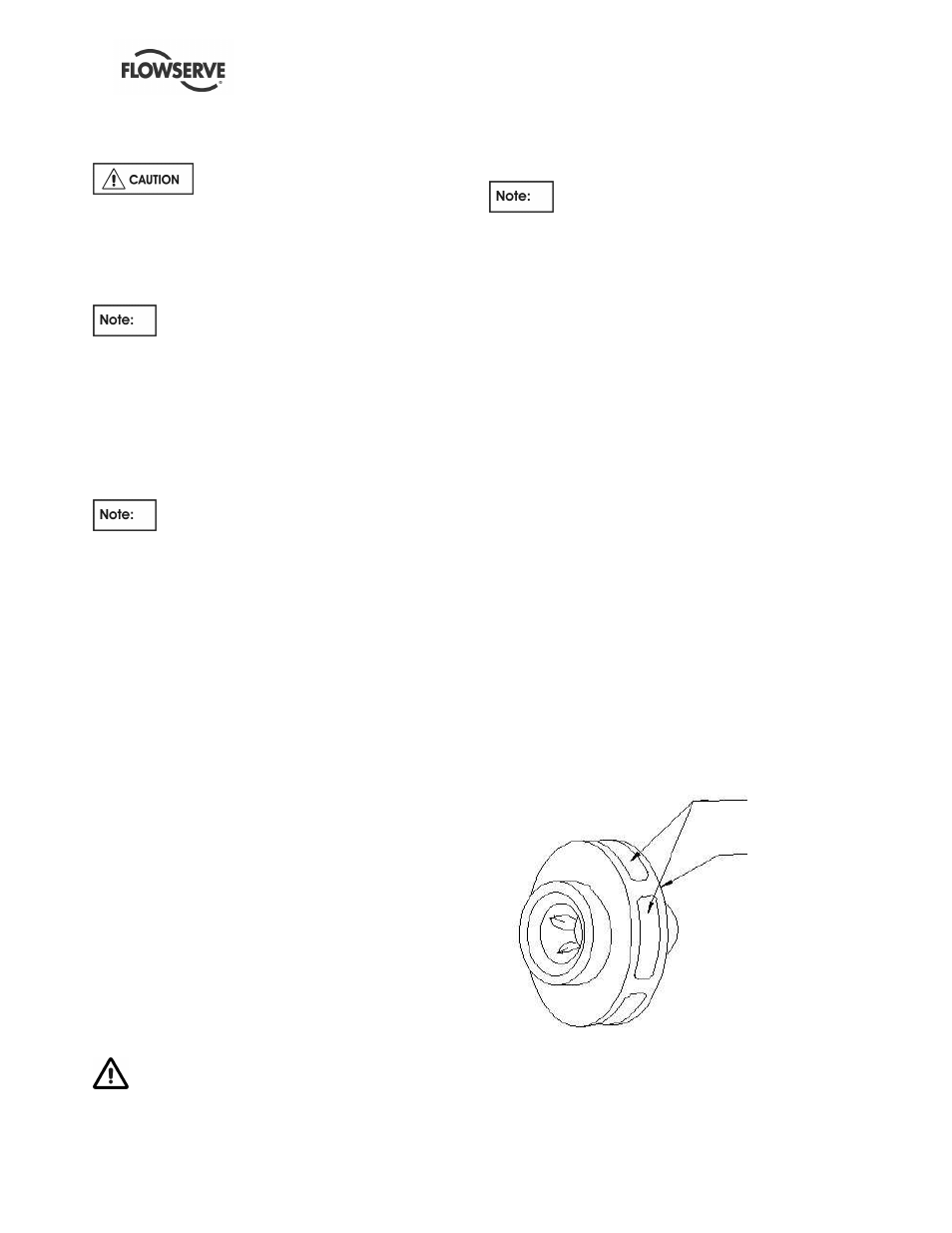
6.6.8
Heating impellers for removal
a) Apply heat (torch with fine tip) to periphery [outer
38 mm (1.5 in.)] of impeller until temperature
reaches 191 °C (375 °F) (minimum) to 204 °C
(400 °F) (maximum). Use "tempilstick" to
determine temperature.
b) Maintaining temperature between. (191 °C –
204 °C (375 °F – 400 °F) at the periphery, apply
heat down through the vane passages, thus
heating the hub.
c) Do not apply heat directly to shaft; this will cause
it to expand.
d) With periphery, shroud and hub at temperature,
remove impeller.
e) If the impeller does not move freely off the shaft,
additional heat may be necessary. This heating
should be started at the periphery of the impeller,
not the hub. (Additional heating of the hub area at
this time will tighten the impeller on the shaft, not
loosen it). If the impeller still fails to come free,
the impeller and shaft should be allowed to cool
completely and the heating process repeated,
starting at Step a).
Heating impeller for removal
f) Remove casing ring [1500] from the next impeller
on the outboard impellers.
2
nd
HEAT
1
st
HEAT