Flowserve DMX User Manual
Page 15
DMX/DMXD/DMXH/DMXDH USER INSTRUCTIONS ENGLISH 85392728 - 10/09
Page 15 of 60
3
PUMP DESCRIPTION
The “DMX” is a multistage single or double suction,
opposed impeller, horizontally split volute pump.
The suction and discharge nozzles are cast integral
with the lower half casing. Rotating parts are
accessible by removing the upper half casing, which
can be removed without breaking suction and
discharge piping.
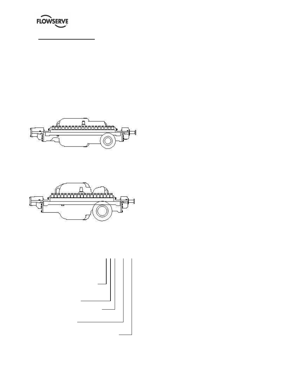
3.1 Configurations
The DMX can have the following configurations:
3.1.1
Single suction
Single suction configuration
Single suction impeller at first stage (DMX)
3.1.2
Double suction
Double suction configuration
Double suction impeller at the first stage (DMXD)
3.2 Name nomenclature
The pump nomenclature is:
3X10DMX10
The 3 is the pump discharge size
The X is the separator
The 10 is the nominal impeller size
The DMX is pump type
The 10 is the number of stages and depending
on pump size, they go from 2 to 14 stages
DMX= Single suction standard pressure
DMXD = Double suction standard pressure
DMXH = Single suction high pressure
DMXDH = Double suction high pressure
3.3 Design of major parts
3.3.1
Casing
The casing provides for immediate containment of
the liquid being pumped, while directing the flow of
liquid from the suction nozzle to the impellers and
subsequently through the volute to the discharge
nozzle.
The casing halves are sealed by the use of a gasket
and are joined together by studs, which are installed
in the lower half casing and fastened with washers
and cap-nuts.
3.3.2
Impellers
The series’ impellers are single suction, enclosed
type, and one-piece construction and are dynamically
balanced. They are fitted with renewable impeller
rings (front and back), which are held in place by
headless set-screws.
The impellers are keyed and have a shrink fit to the
pump shaft. They are held in axial position by a split
ring.
3.3.3
Casing rings
Casing rings are positioned over the impeller front
rings. These rings are tubular and renewable.
3.3.4
Channel rings
Renewable cast channel rings are positioned over
the impeller back rings. They divide the casing into
stages. These rings are horizontally split and are held
together by shoulder screws or dowel pins.
3.3.5
Center sleeve
A renewable type center sleeve is used under the
center bushing. The center sleeve is tubular and
keyed to the shaft (via the impeller key).
3.3.6
Center bushing
The renewable center bushing is horizontally split,
and the two halves are held together by socket head
cap screws and taper dowel pins. It is held in position
by the raised annular ring of the bushing engaging
the annular groove in the casing. The center bushing,
in conjunction with center sleeve, divides the casing
at the center (back to back) impellers.