Location of can termination jumper, Location of can termination jumper -12, Figure 42: rs422 surge suppressor -12 – Daktronics AF-3160-34-R,A User Manual
Page 48
1.
To replace the surge board, first disconnect the
signal connections (refer to
on the
right).
Figure 42: RS422 Surge Suppressor
2.
The surge suppressor is held in place with four
screws. Carefully remove them using a 3/16”
nut driver.
3.
Install the new surge suppressor, replace the
screws, and reconnect power and signal cables.
Location of CAN Termination Jumper
Temperature and light sensors are controlled as part of a CAN network. For the CAN
network to work correctly, the network must be terminated at both ends of the
network. This is true for a single display or for multiple displays. The correct
terminations are completed during the building process. However, if the order or
number of displays is changed on-site, the terminating jumper may need to be
relocated.
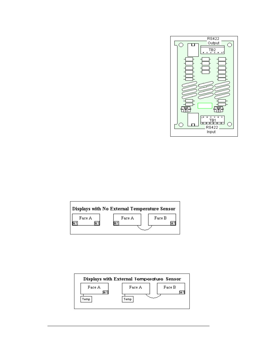
W1 is the necessary location of the terminations.
Figure 43: Displays with No External Temperature Sensor
In the case of those displays that utilize a temperature sensor, the sensor is internally
terminated. Therefore, only one other termination needs to be made at the output of
the last sign in the network. The most common input location for the temperature
sensor is to the first or primary display in the network.
Figure 44: Displays with External Temperature Sensor
Maintenance and Troubleshooting
4-12