Transformer and rfi filter, Transformer, Rfi filter – Daktronics AF-3160-34-R,A User Manual
Page 40: Transformer and rfi filter -4, Figure 35: power termination box -4
Transformer and RFI Filter
Reference Drawings:
Assy, Power Termination Box ..................................... Drawing A-127361
Schematics ...............................................................Refer to Appendix A
Maintenance and Troubleshooting
4-4
f
Trans ormer
The transformer is located in the upper portion of the power termination box. To
replace the transformer, first disconnect and label all the wires attached to it. Turn
off power to the display before removing the wires. Then release the hardware,
securing it to the inside of the enclosure. Position the new transformer in its place,
and tighten it down. Re-connect all the wires using the display’s schematic as a
reference.
RFI Filter
The RFI electrical filters are mounted above and to the side of the power termination
box (Z1 and Z2 in Drawing A-127361). Like the transformer, first removing all
connecting wires, and then releasing the attachment hardware can replace the filters.
Install the new filter using the display’s Schematic as a wiring reference.
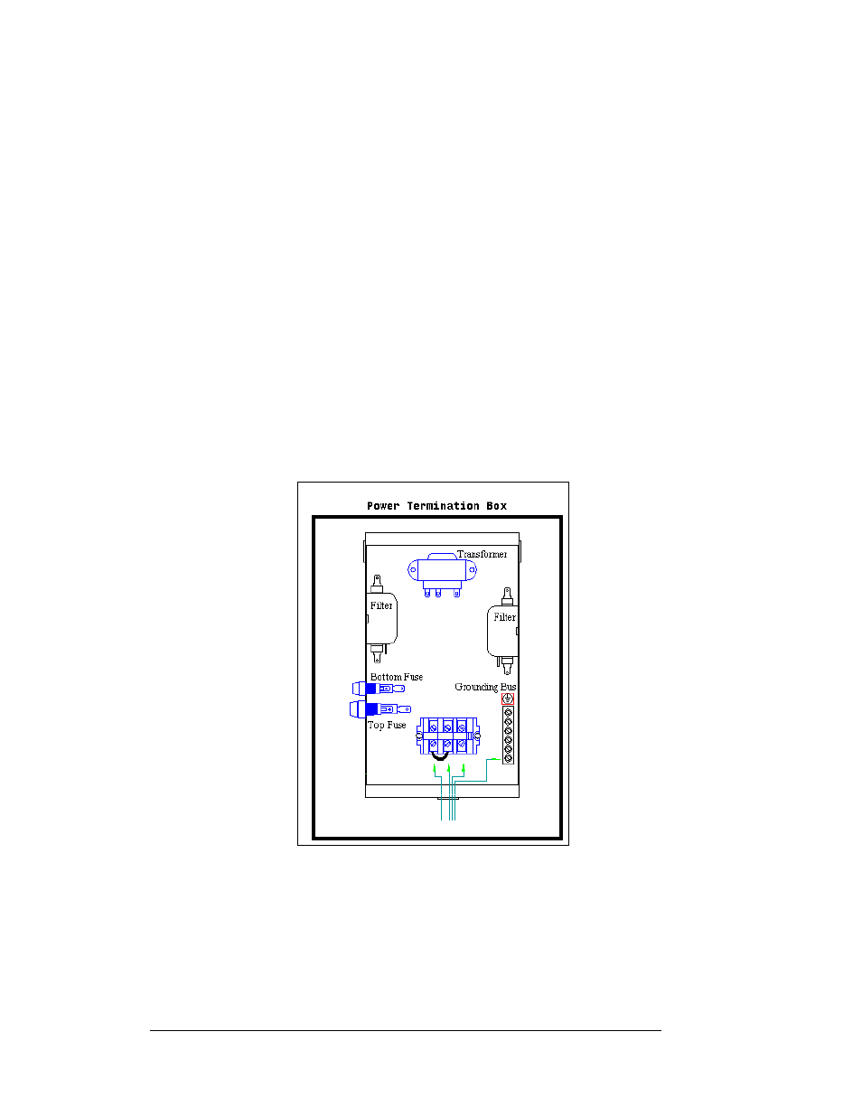
Figure 35: Power Termination Box