Power connection, Power connection -8 – Daktronics AF-3160-34-R,A User Manual
Page 26
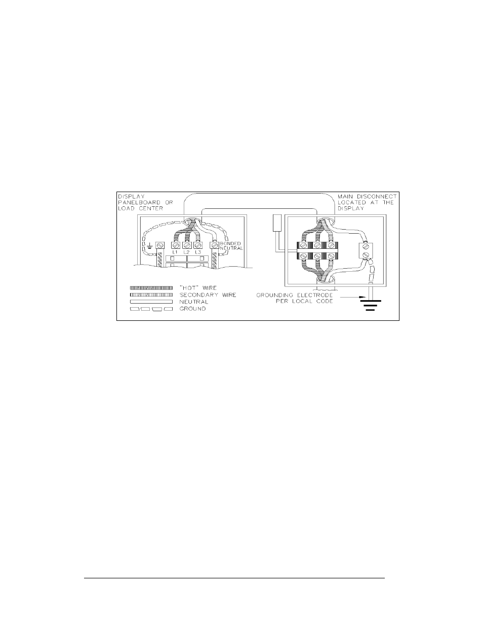
Installation with Only a Neutral Conductor Provided
Installations where no grounding conductor is provided must comply with article
250-32 of the National Electrical Code. If the installation in question meets all of the
requirements of article 250-32, the following guidelines must be observed:
• Connect the grounding electrode cable at the local disconnect, never at the
sign panel board.
• A disconnect that opens all of the ungrounded phase conductors should be
used.
• The neutral and the ground conductors should be bonded in the sign panel
board.
below for installation details.
Figure 21: Installation with only Neutral Conductor Provided
Power Connection
Reference Drawings:
Assy; Power Termination Box ..................................... Drawing A-127361
Schematics ...............................................................Refer to Appendix A
Incoming power is connected within the power termination enclosure. Complete the
following steps to terminate the hot and neutral wires at the termination block within
the enclosure. Refer to Drawing A-127361 and the appropriate Schematic for your
display size.
1. Access the enclosure by removing the left bottom two modules as described
in Section 3.5.
2. Route the power cables through the power conduit in the rear of the sign
and to the enclosure.
3. Connect the white neutral wire to neutral bus.
4. If one power line is being terminated (120VAC), connect the black “hot”
wire to L1. Install jumper per Drawing A-127361.
5. If two power lines are being terminated (120/240VAC). Connect the second
“hot” wire to L2 and remove the jumper.
6. Connect the green grounding wire to the grounding bus E41. Refer to
Electrical Installation
3-8