Venus 1500 radio, Venus 1500 radio -15, Figure 31: radio display layout -15 – Daktronics AF-3160-34-R,A User Manual
Page 33: Figure 32: client radio display connection -15
Signal Converter to Fiber Board
Signal
Converter
Field Cabling
Fiber Control
Card
J2 Transmit (TX1)
(Color Varies)
J5 Receive (RX2)
J3 Receive (RX1)
(Color Varies)
J4 Transmit (TX2)
Venus 1500 Radio
Reference Drawings:
System Riser Diagram, QC Outdoor Radio, Gen 2 ..... Drawing A-185359
Schematic, Signal Wiring, Internal, W/Quick Connect. Drawing B-177662
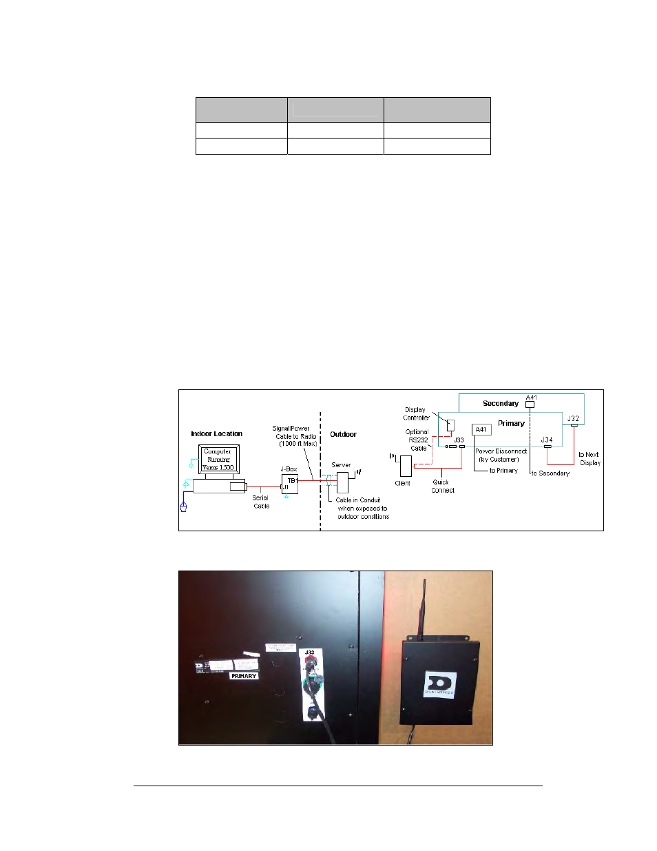
A radio-controlled display requires a Server radio connected to the control computer
and a Client radio at the display. The radios must be in line-of-site of each other. The
Client radio is provided with 25 feet of weather resistant pre-terminated cable. One
end of the cable is pre-terminated to TB1 inside the radio enclosure, and a quick
connect plug is terminated at the other end of the cable. The cable will be terminated
to the display with the quick connect plug to J33 on the display as shown in
. Refer to Drawing A-185359 and
for the system riser. Additional
drawings for the Server Connections are in the Venus 1500 Radio Manual
(ED13932).
Figure 31: Radio Display Layout
Figure 32: Client Radio Display Connection
Electrical Installation
3-15