Rs232, Rs232 -10, Figure 23: rs232 display layout -10 – Daktronics AF-3160-34-R,A User Manual
Page 28
RS232
Reference Drawings:
System Riser Diagram, RS232 ................................... Drawing A-174341
Schematic, Signal Wiring, Internal, W/Quick Connect Drawing B-177662
Controller, Galaxy, 8-conn., J1087.............................. Drawing B-177838
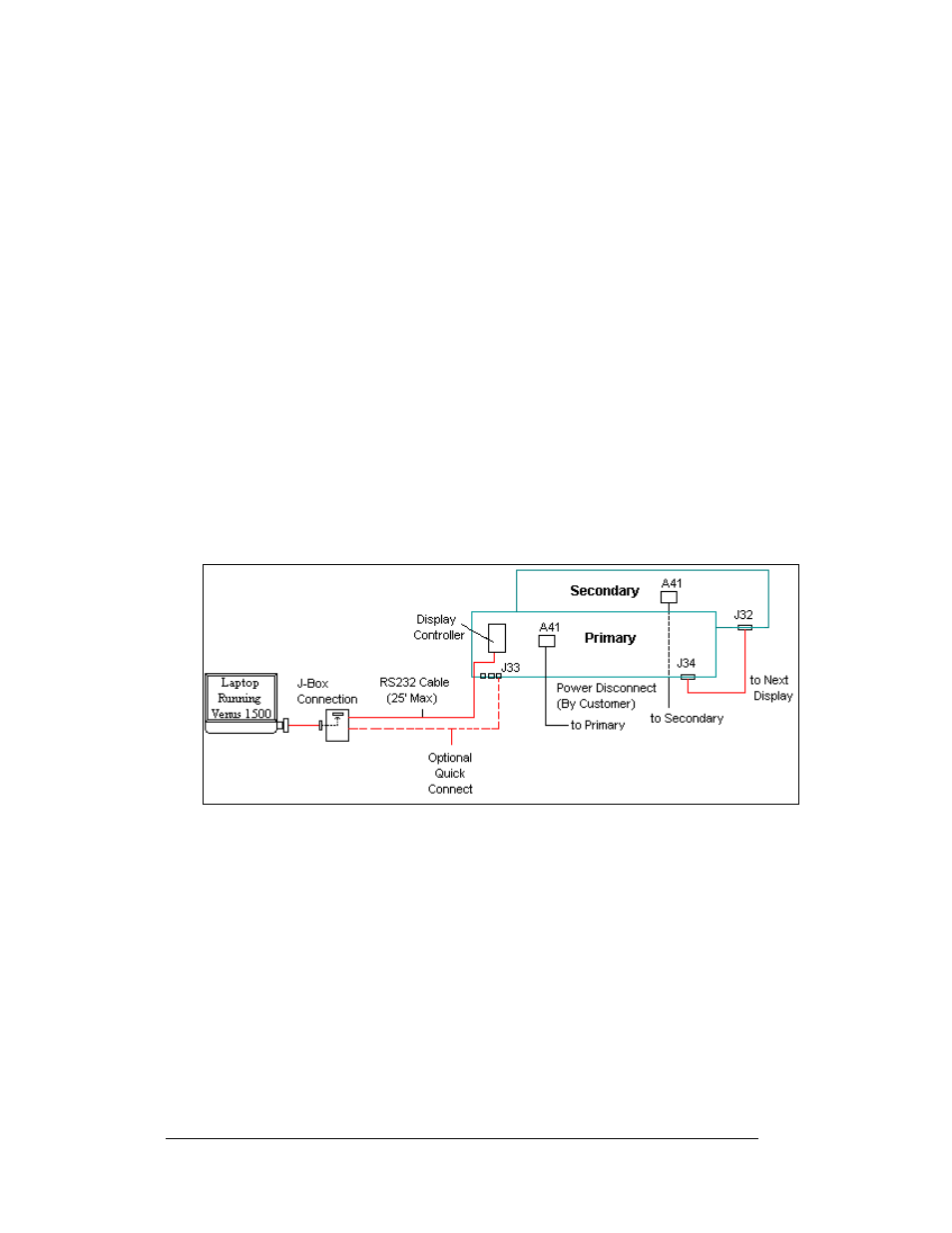
The RS232 controlled display requires the use of a J-box within 25 feet of the
display, as shown below in
. From the J-box to the display, the signal may
be connected using a quick connect cable or wired directly to the controller inside
the display. The cable from the J-box to the display must be routed though conduit.
Do not run signal and display power through the same conduit.
1. If using a quick connect cable, connect from the J-box to J33 on the back of
the display.
2. When connecting directly to the display, terminate one end to the terminal
block at the J-box and the other end of the wire to the 6-position terminal
block on the controller labeled “RS232 IN” (A31-TB1).
Drawing B-177662, show the terminal block wiring, and Drawing B-
177838 shows the controller.
The controlling laptop computer connects to the J-box through the serial cable (refer
to Drawing A-174341).
Figure 23: RS232 Display Layout
Electrical Installation
3-10