Modem, Modem -10, Figure 39: modem -10 – Daktronics AF-3160-34-R,A User Manual
Page 46: Figure 40: modem jumper location -10
Modem
Reference Drawings:
Detail; AF-3160-8/16, Power/Control Corner .............. Drawing A-178959
Detail; AF-3160-24/32/40/48, Power/Control Corner .. Drawing A-178960
If a modem was included with the display, it is located inside the display next to the
controller board. Refer to Drawing A-178959 or A-
178960 for modem location.
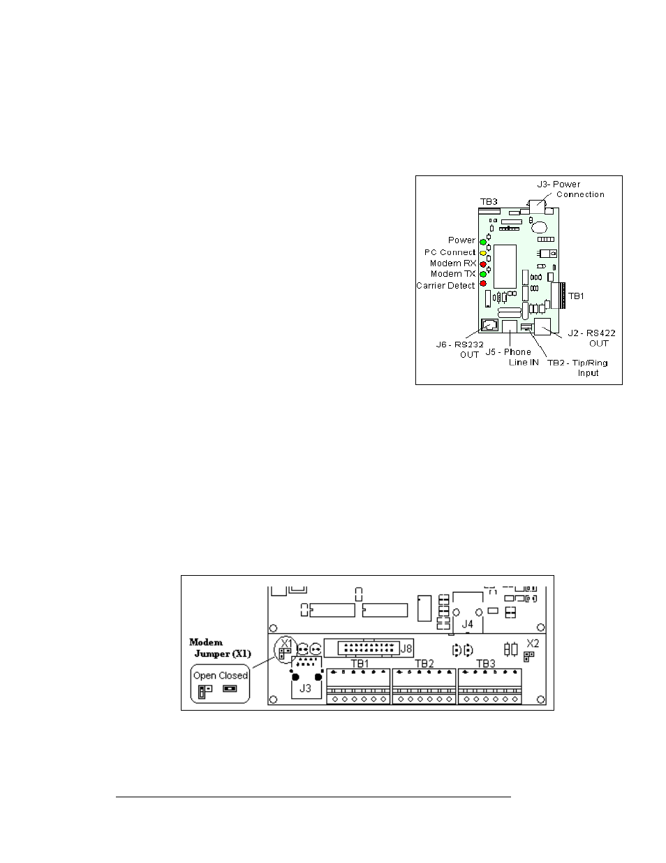
Figure 39: Modem
1. To replace a modem, first disconnect the power
and signal connections (refer to
the right for the location of the connectors).
2. The modem is held in place with four screws.
Remove the screws using a 3/16” nut driver,
and lift the modem out of the display.
3. Install the new modem, replace the screws, and
reconnect power and signal cables.
The modem module has five LEDs.
•
The power LED should remain lit while power
is applied to the modem.
•
The modem RX and TX will flash when
communicating.
•
The carrier detect LED will light when the
modem has established communication to
another modem.
•
The PC connect LED is not used in the display application.
The modem board also has several input and output jacks:
•
J3 is the power input for 12VAC
•
TB2 is a phoenix connector to terminate the Tip and Ring wires
•
J5 is an RJ11 jack for termination of a pre-terminated phone line
•
J6 is the RS232 RJ45 output to the controller
•
J2, TB1, and TB3 are not used in this display application
A modem system requires a jumper (X1) to be closed on the controller board. The
jumper position is only recognized on power up. Refer to
location, and the jumper settings.
Figure 40: Modem Jumper Location
Maintenance and Troubleshooting
4-10