Service and diagnostics, Service and diagnostics -3, 4 service and diagnostics – Daktronics AF-3160-34-R,A User Manual
Page 39
Maintenance and Troubleshooting
4-3
4.4 Service
and
Diagnostics
Reference Drawings:
Detail; AF-3160-8/16, Power/Control Corner............... Drawing A-178959
Detail; AF-3160-24/32/40/48, Power/Control Corner... Drawing A-178960
Comp. Layout Diagram ............................................ Refer to Appendix A
Schematics.............................................................. Refer to Appendix A
Remember: Disconnect power before servicing any internal components.
The following sub-sections address servicing of the following display components:
•
transformer, RFI filter
•
controller
•
modules, drivers and power supplies
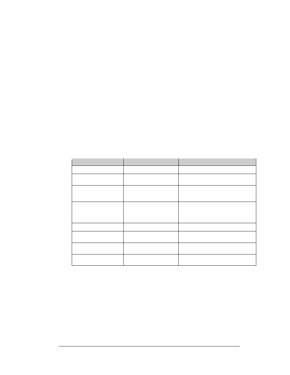
The sub-sections also address any diagnostic LEDs, fuses, and signal/power
connectors found on the unit. On the Component Layout Diagrams, the
components are denoted as follows:
Component
Denoted As
Location
Filter and Transformer
0A-1215-4002 (120 VAC)
Inside the power termination box
Controller
0A-1229-0005
Inside the controller/power panel
(behind the bottom left module)
Modules
0A-1208-3005
0A-1208-3006
0A-1208-2504
Over entire face of the display
(includes driver)
Power Supplies
0A-1213-4022-4A
0A-1213-4026-4A
0A-1213-4013-3R
0A-1213-4034-RG
Behind modules (refer to the display’s
Schematic)
Light Detector
0P-1247-0003
Behind\below the bottom left module
Modem 0P-1279-0003
Refer to Drawing A-178959 or
Drawing A-178960
Fiber Board
0P-1127-0024
Refer to Drawing A-178959 or
Drawing A-178960
RS422 Surge Card
0P-1146-0031
Refer to Drawing A-178959 or
Drawing A-178960