Figure 11: phoenix connector -2, Figure 12: mate-n-lok connector -2, Figure 13: rj45 connector -2 – Daktronics AF-3160-34-R,A User Manual
Page 20: Figure 14: rs232/6-pin quick -2
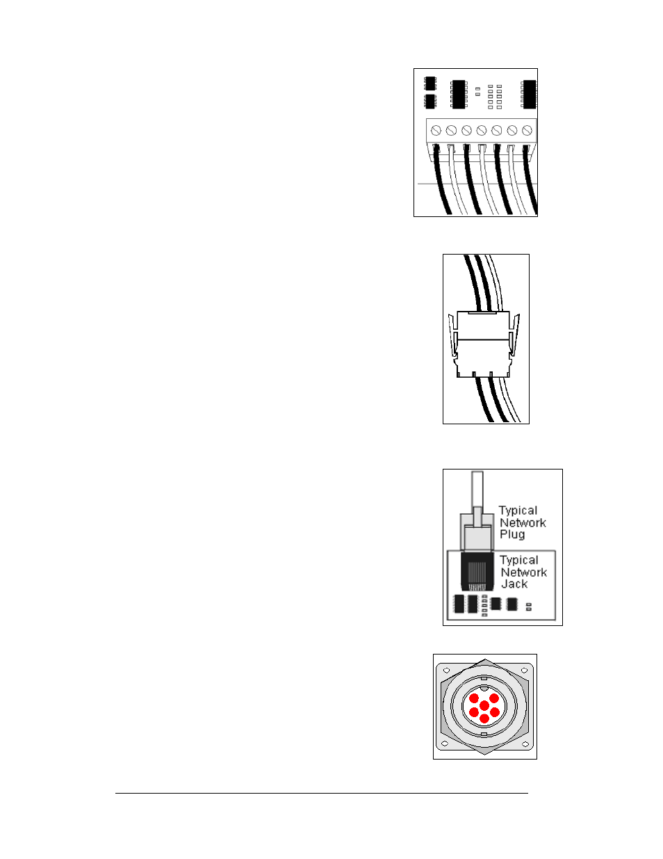
Figure 11: Phoenix Connector
3. Phoenix
™
-Style Connectors:
Phoenix-style connectors, which are usually
green, are often used for signal termination on
circuit boards. Refer to
Strip one-quarter inch of insulation from the
wire prior to termination. To remove a wire,
turn the above screw counter-clockwise to
loose the connectors grip on the wire. To insert
a wire, push the bare wire into the connector
and turn the above screw clockwise to lock the
wire into place.
4. Mate-n-Lok
™
Connectors:
The Mate-n-Lok connectors found in the displays are
white and come in a variety of sizes.
on the
right illustrates a four-pin Mate-n-Lok connector. To
remove the plug from the jack, squeeze the plastic
locking clasps on the side of the plug and pull it from
the jack.
Figure 12: Mate-n-Lok
Connector
5. Phone Jacks (RJ11/RJ45 Connectors):
RJ connectors, as seen in
on the lower right,
are similar to the telephone connectors found in
homes. In order to remove this plug from the jack,
depress the small clip on the underside of the plug.
Before replacing an RJ connector, spray it with
DeoxIT
™
contact cleaner to remove any foreign matter
that may cause signal problems. In addition, apply a
generous amount of CaiLube
™
protector paste to the
plug before inserting it into the jack. This paste will
protect both the plug and the jack from corrosion.
Figure 13: RJ45
Connector
The six-pin connectors found in the display are keyed
connectors, meaning that they will only go together
one way and should not be forced. To remove the
connector squeeze the plastic tab and gently pull the
plug from the jack.
6. Quick Connect Jack:
The display uses quick connect jacks for the
connection of the temperature sensor, the client radio,
and connection of the primary to the secondary or
mirror display. The quick connect jacks are located
on the back of the display and when not used the
attached cover should be kept closed.
Figure 14: RS232/6-
pin Quick Connect Jack
To attach the cable to a jack, make sure to line up
the plug to match the jack, push the plug in then
turn the outer collar to lock in place.
illustrates the 6-pin quick connect jack.
Electrical Installation
3-2