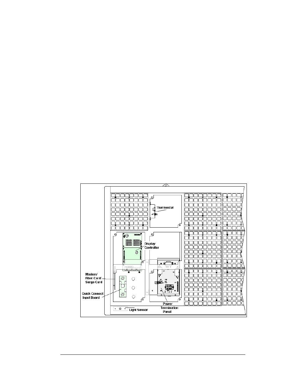
Light detector, Light detector -9, Figure 38: power/control corner -9 – Daktronics AF-3160-34-R,A User Manual
Page 45
Complete the following steps to remove a power supply from the display:
1.
Remove the module directly in front of the failed power supply.
2.
Disconnect and label all the wires connected to the power supply.
3.
Remove the hardware holding the power supply in place to free the unit.
4.
Follow these steps in reverse order to install a new power supply. Refer to
the display’s Schematic when reconnecting the wires.
Light Detector
Reference Drawings:
Schematics.............................................................. Refer to Appendix A
Comp. Layout Diagram ............................................ Refer to Appendix A
The light sensor is internally mounted and wired at Daktronics. It is located in the
bottom left corner on the front of the primary display as shown in
. In the
Component Layout Diagram the sensor is identified as assembly 0A-1241-4013
(LT). The light and temperature sensors are part of the same CAN network and are
addressed accordingly. The light sensor is address 2.
A 4-conductor cable connects the light sensor to the controller. The cable is
terminated at the terminal block on the light sensor and to a jack that plugs into the
controller. When the displays are mounted back-to-back, only the primary side has a
light sensor
Figure 38: Power/Control Corner
Maintenance and Troubleshooting
4-9