Signal termination between two (or more) signs, Rs422 interconnection, Signal termination between two (or more) signs -16 – Daktronics AF-3160-34-R,A User Manual
Page 34: Rs422 interconnection -16, Figure 33: display interconnect -16, Figure 34: rs422 interconnection -16, 8 signal termination between two (or more) signs
3.8 Signal Termination Between Two (or More) Signs
Reference Drawings:
System Riser Diagram Fiber ....................................... Drawing A-174344
Schematic, Signal Wiring, Internal, W/Quick Connect Drawing B-177662
Controller, Galaxy, 8-conn, J-1087.............................. Drawing B-177838
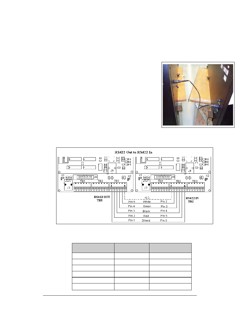
Figure 33: Display Interconnect
RS422 Interconnection
The quick connect cable is the most common method of
terminating signal between two displays. The cable goes
from the RS422 OUT (J34) on the primary display to the
RS422 IN (J32) on the secondary display. See Figure 33
on the right.
If the displays are not back-to-back, or are too far apart for
the interconnect cable to reach, a 4-conductor shielded
cable of the correct length is used as shown in
Figure 34
.
One end will connect at the “RS422 OUT” 6-position
controller board terminal block (A31-TB3) in the first
display, and terminate on the “RS422 IN” 6-position
controller board terminal block (A31-TB2) on the second
display. When not using the quick connect cable, wire
must be in conduit.
Figure 34: RS422 Interconnection
RS422 Interconnection
Primary - RS422
Out (A31-TB3)
Field Cabling
Secondary - RS422
IN (A31-TB2)
Pin 1 (GND)
Shield
Pin 6 (GND)
Pin 2 (D2OUT-N)
Red
Pin 5 (D1IN-N)
Pin 3 (D2OUT-P)
Black
Pin 4 (D1IN-P)
Pin 4 (D2IN-N)
Green
Pin 3 (D1OUT-N)
Pin 5 (D2IN-P)
White
Pin 2 (D1OUT-P)
Pin 6 (Shield)
Pin 1 (Shield)
Electrical Installation
3-16