Rs422, Rs422 -11, Figure 24: rs232 j-box to controller board -11 – Daktronics AF-3160-34-R,A User Manual
Page 29: Figure 24
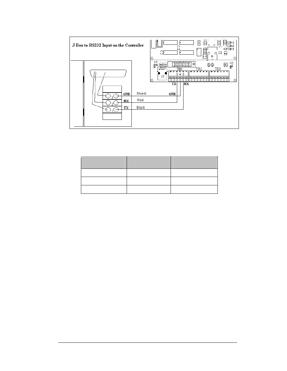
Figure 24: RS232 J-box to Controller Board
J-Box to Controller Board (A31)
J-Box Terminal
Block
Field Cabling
Controller Board
TB1 (RS232 In)
Pin 1 (TX-P
Black
Pin 5 (RX-1)
Pin 2 (RX-P)
Clear/Red
Pin 3 (TX-1)
Pin 3 (GND)
Shield
Pin 4 (GND-N)
RS422
Reference Drawings:
System Riser Diagram, RS422 .................................... Drawing A-174135
Schematic, Signal Wiring, Internal, W/Quick Connect. Drawing B-177662
A RS422 controlled display requires the use of signal converter (0A-1127-0237) near
the computer. From the signal converter, cable is run to the surge board assembly in
the display. The cable from the signal converter to the display must be routed though
conduit. Do not run signal and display power through the same conduit. Refer to
and Drawing A-174135 for system layout.
1. If using a quick connect cable, signal will run from the signal converter to a
box at the base of the display. From that junction box, connect to J32 on
the back of the display.
2. When connecting directly to the display, terminate one end at the signal
converter and the other end of the wire to the 6-position terminal block on
the surge board assembly labeled “RS422 IN” (A34-TB1). Drawing
B-177662 and
show the terminal block wiring.
Electrical Installation
3-11