Light/photo sensor installation, Troubleshooting, Light/photo sensor installation -8 – Daktronics DF-1030 User Manual
Page 36: Troubleshooting -8, Figure 21: internal light sensor -8, 4 light/photo sensor installation, 5 troubleshooting
• J5 is an RJ11 jack for termination of a pre-terminated phone line (if
needed).
• J2, TB1, and TB3 are not used in this application.
4.4 Light/Photo Sensor Installation
Reference Drawing:
Light
Sensor
Installation, G3 ....................................... Drawing A-183775
Mechanical Specification Drawings ..........................Refer to Appendix A
Displays in the DataMaster series use a light sensor to regulate sign dimming
functions. Use Drawing A-183775 and the following instructions to install the photo
sensor in your DataMaster Rate display. If the sign or sign system has more than one
display, install the light sensor in the primary/host display only.
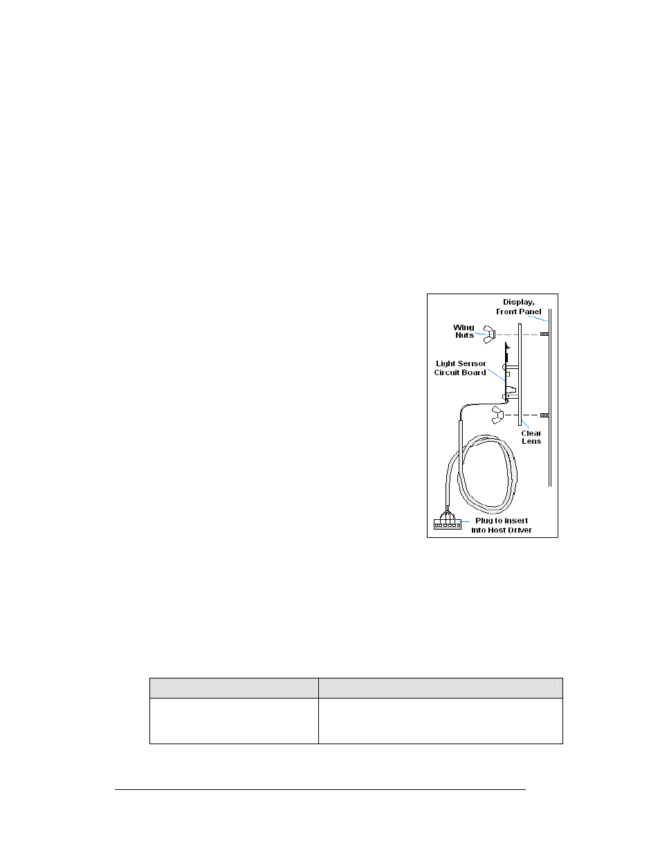
Figure 21: Internal Light Sensor
1. Remove the screws on the front of the display and
open the hinged access door.
2. Locate and remove the
5
/
8
" plastic plug from front
panel of the display. The location of the plug varies
by model. Refer to the Mechanical Specification
Drawings for model-specific information.
3. There are two 6-32 studs above and below the
plughole. Position the internal light sensor
assembly (Daktronics part #0A-1279-0203) is
positioned on the studs, with the clear lens toward
the front of the cabinet and the cable at the bottom.
Secure the sensor with the provided plastic wing
nuts.
4. Route the signal cable to the driver and insert the
6-postion plug into the mating jack on the driver,
TB1.
5. Close the hinged access doors and replace the
screws.
4.5 Troubleshooting
This section lists potential problems with the display, indicates possible causes, and
suggests corrective action. This list does not include every possible problem, but it
does represent some of the more common situations that may occur. (Refer to the
appropriate manual for a list of potential problems with add-on or separately
mounted message centers.
Symptom/Condition
Possible Cause
Entire display fails to work
• Check for proper line voltage at termination panel
• Check connections from power supply to driver
• Check power LED on driver and power supplies
4-8 Maintenance
and
Troubleshooting