Modem (indirect), Modem (indirect) -8, Figure 10: modem controlled display layout -8 – Daktronics DF-1030 User Manual
Page 24
Connection from J-box to Server Radio Enclosure
J-Box
TB2 on Server
Pin#
Function
Cable
Color
Pin#
Function
Pin 1
Power
Red
Pin 1
Power
Pin 2
422 RX-P
White
Pin 2
422 TX-P
Pin 3
422 RX-N
Green
Pin 3
422 TX-N
Pin 4
422 TX-P
Brown
Pin 4
422 RX-P
Pin 5
422 TX-N
Blue
Pin 5
422 RX-N
Pin 6
GND
Black
Pin 6
GND
Notes:
1. The cable from the client radio to the display can to be routed through
conduit or the display pole to protect it from weather and vandalism. The
cable is weather and sunlight resistant.
2. The Server and Client radios must have a clear line-of-sight path and not be
more than 1500 feet apart.
3. A current-loop j-box is often mounted at the base of the display pole in case
of problems with communication though the radio network.
4. For additional connection and operation information see ED-13894:
DataMaster Radio Installation Manual.
Modem (Indirect)
Reference Drawings:
Modem Installation; 4 Col MASC Drvr. Enc. ............... Drawing A-177039
Quick Install, DF-1030 & DF-1040 Rate Displays ....... Drawing A-177150
System Riser Diagram, Modem Setup ........................ Drawing A-200552
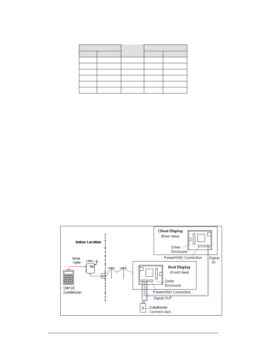
A modem controlled display uses a DataMaster controller connected to a modem/
j-box, to call a second modem in the Rate Display. The DataMaster hand-held
controller will receive its power from the j-box. A wall pack transformer powers the
j-box. The display layout is shown in
and Drawing A-200552.
Figure 10: Modem Controlled Display Layout
3-8 Electrical
Installation