Host/client definitions and address settings, Host/client definitions, Address settings – Daktronics DF-1030 User Manual
Page 26: Host/client definitions and address settings -10, Figure 13: example address settings -10
Host/Client Definitions and Address Settings
Reference Drawings:
4 Column MASC Driver Specifications........................ Drawing A-166216
8 Column MASC LED Driver Specifications................ Drawing A-167237
16 Col. MASC Driver Specifications............................ Drawing A-184475
Host/Client Definitions ................................................. Drawing A-185236
Host/Client Definitions
One driver at each sign installation is designated as the “host driver.” This driver
receives its signal directly from the controller on the “Signal IN” terminals, and it is
the only driver that is connected to the photo/light sensor. The “Signal OUT”
terminals are used to connect to “client drivers.” Refer to Drawing A-185236 for an
illustration of the client/host driver display setups.
Select the host driver by inserting the Protocol 4 plug into the 5-pin protocol jack
(J20.) For protocol jack location, refer to Drawings A-166216, A-167237 or
A-184475 for your specific display driver.
The 12 V DC terminals connected to the host driver (see “Signal Connections” in
) run to the controller junction box. This output is used to power the
DataMaster 100 controller.
All other drivers in the display system are client drivers. These drivers receive signal
from the host driver on the “Signal IN” terminals and can re-drive this signal to other
“client drivers” on the “Signal OUT” terminals.
Some multiple-module signs use “mirror/slave displays.” The terms “master/slave”
or “primary/mirror” should not be confused with “host/client. ” Mirror/slave displays
do not contain a driver and may use either the client or host digit outputs.
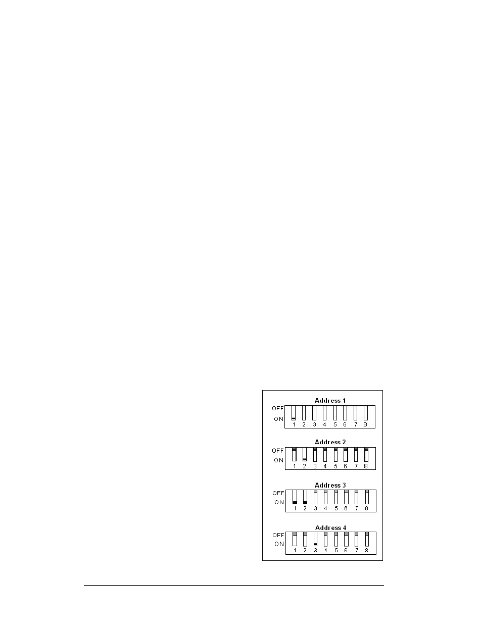
Address Settings
The address of each driver is set using an
Figure 13: Example Address Settings
8-position DIP-switch (S1), and the address
is based on that driver’s position in the sign
or display system. If a single-line sign is
used, the address will typically be Address
“01.” This means that switch 1 is turned
“ON” and the remaining 7 switches are in
the “OFF” position. This is the default
address set when each display is shipped. In
multiple-product displays, the address
determines which line of information is
shown on the driver’s digits. The switch is
set using a binary address. Use the table and
the examples in
for setting the
address.
3-10 Electrical
Installation