Segmentation and digit designation, Replacing an led driver, Segmentation and digit designation -4 – Daktronics DF-1030 User Manual
Page 32: Replacing an led driver -4, Figure 17: digit designation -4
Segmentation and Digit Designation
Reference Drawing:
Segmentation, 7 Segment Bar Digit .............................. Drawing A-38532
In each digit, certain LEDs always
go on and off together. These
groupings of LEDs are referred to
as “segments.” Drawing A-38532
illustrates digit segmentation. It
also details which connector pin is
wired to each digit segment and the
wiring color code used throughout
the display.
4-4 Maintenance
and
Troubleshooting
The Electrical Specification
Drawings specify the driver
connectors controlling the digits.
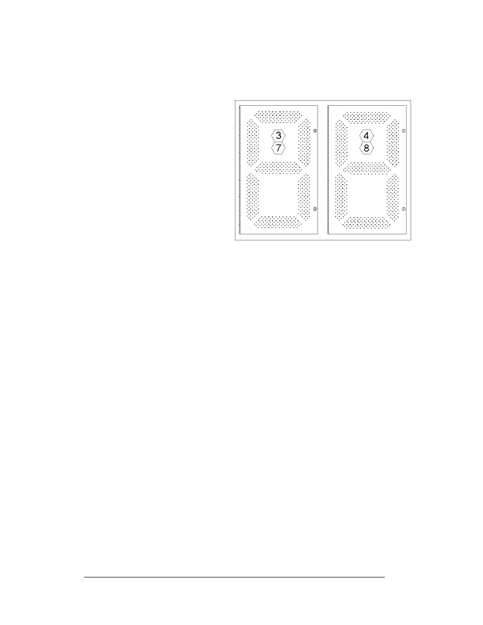
Numbers displayed in hexagons in
the upper half of each digit, as
shown in
connector or connectors are wired to that digit. Larger digits, like the 36" digits
shown in Figure 17, are each wired to two connectors. (Digits for a 48” display use
four connectors for each digit.)
Figure 17: Digit Designation
Replacing an LED Driver
Reference Drawings:
4 Column MASC LED Driver Specifications................ Drawing A-166216
8 Column MASC Driver Specifications........................ Drawing A-167237
16 Col. MASC Driver Specification.............................. Drawing A-184475
Electrical Specification Drawings .............................Refer to Appendix A
Mechanical Specification Drawings ..........................Refer to Appendix A
Drivers are typically mounted inside the display and immediately behind a digit, but
location and mounting varies by model. Refer to the Electrical and Mechanical
Specification Drawings for the location of your driver. All displays in this manual
are front-accessible.
To replace the driver in the display enclosure:
1. Open the digit panel or display face panel as described in Section 4.2.
2. Remove the cover from the driver enclosure.
3. It is helpful to have the cables labeled as to which was removed from which
connector.
4. Disconnect all connectors from the driver. Release each connector by
squeezing together the locking tabs as you pull the connector free.
Note: When reconnecting, remember that these are keyed connectors and
will attach in one way only. Do not attempt to force the connections.
5. Remove the wing nuts securing the driver to the inside of the enclosure.