Radio (direct), Radio (direct) -6 – Daktronics DF-1030 User Manual
Page 22
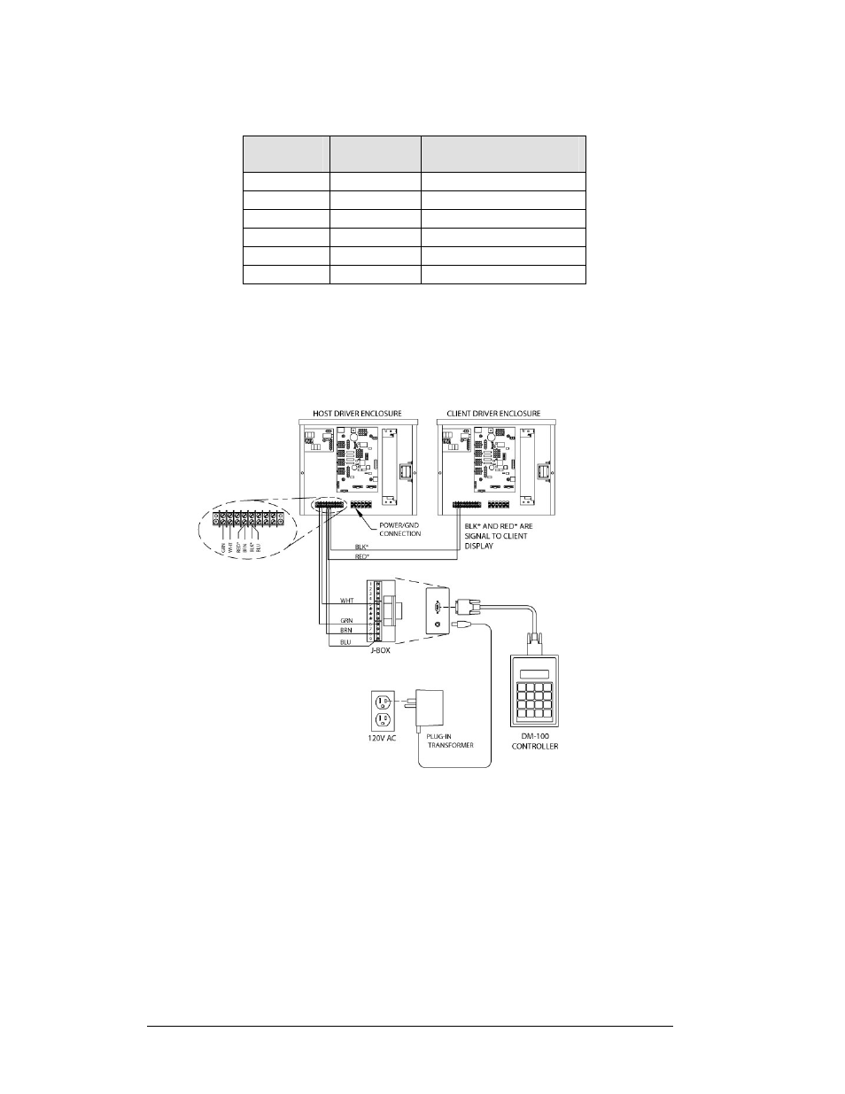
J-Box to Driver Enclosure Input Jack
J-Box
Pin#
Cable
Color
Enclosure Terminal
Block
Pin 1
Red
12V DC Out (+) pin 7
Pin 5
Black
12 V DC Out (-) Pin 8
Pin 5
White
Signal IN (-) Pin 2
Pin 6
Green
Signal IN (+) Pin 1
Pin 8
Brown
Signal OUT (+) Pin 4
Pin 9
Blue
Signal OUT (-) Pin 5
If using the DataMaster handheld controller at an indoor location, two pairs of signal
wires (white/green and blue/brown) will need to be connected to the j-box. A wall
pack transformer, plugs into the indoor j-box, and provides power to the DataMaster
controller. The distance from the indoor j-box to the host driver can up to 2000 ft.
Refer to Figure 7
and Drawing A-175342 for system layout and signal connections.
Figure 7: Direct Connection from Indoor Location
Radio (Direct)
Reference Drawings:
Quick Install, DF-1030 & DF-1040 Rate Displays ....... Drawing A-177150
System Riser Diagram, Server/Client Setup ............... Drawing A-199834
A radio controlled display uses the DataMaster controller connected to a j-box. The
j-box is then wired to a server radio attached to the building. A second radio, called
the client is connected to the Rate display. The DataMaster hand-held controller and
server radio receive their power through the j-box. A wall pack transformer powers
the j-box. The client radio receives its power from the display. The display layout is
shown in Figure 8
and Drawing A-199834.
3-6 Electrical
Installation