Cloud Electronics DCM1 User Manual
Page 34
DCM1 & DCM1e Installation and User Guide v1.0
34
The default setting is PAGE Input. This configures the
connector to be used for Zone selection with a third-party
paging system. The next option, PAGE Output,
should be
used when the DCM1 is connected to a Cloud PM or CDPM
paging microphone(s), and per-zone contact closures are
required as tallies, normally for volume restoration purposes.
See page 23 for full details of how to wire the
PAGING
ACCESS connector when used for these purposes.
The third option configures the
PAGING ACCESS
connector as a GPIO (General-purpose Input-Output) port.
In this mode, it cannot be used in conjunction with paging
microphones for either zone selection or zone tally outputs.
When set as a GPIO port, serial data received at the
RS232
INTERFACE (and/or ETHERNET INTERFACE in the
case of the DCM1e) can set individual channels logic-high
or logic-low (outputs), or the status of channels can be
interrogated and reported using RS-232 serial data (inputs).
The default allocation is with all eight channels of the
port as outputs, denoted on the lower row of the display
as GP OOOOOOOO. Turning the rotary control further
clockwise re-assigns each channel in turn as an input, e.g.,
GP IOOOOOOO
, GP IIOOOOOO, and so on. Note that
channels set as inputs must always form a consecutive block
numbered ‘up’ from pin 1; likewise channels set as outputs
must always form a consecutive block numbered ‘down’
from pin 8. See page 67 for more details of how to use the
PAGING ACCESS connector as a GPIO port.
The numeric buttons are not used in this function.
UTILITY
Configure Access Connector may be accessed by
clicking the SYSTEM tab, and setting Access Contacts
to either Input or Output* in the Paging Mic
area. Click Send System to transmit the new setting.
* An updated version of the Utility Tool including GPIO configuration of the
Access Connector will be available during 2014.
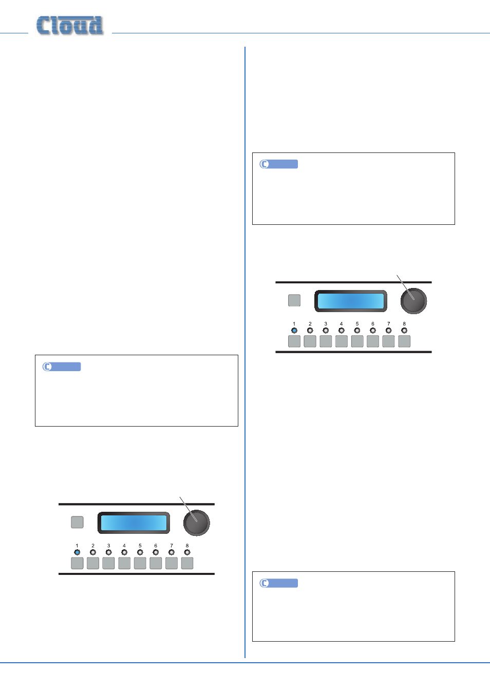
PM Zone Offset
SELECT INPUT
PM Zone Offset
0
Rotary Control sets offset
The purpose of the PM Zone Offset menu function is to
permit Cloud PM and CDPM paging microphones to address
more than 8 zones.
Cloud PM and CDPM systems can address up to 16 Zones
(model-dependent). To permit paging of Zones 9 and higher
in a system utilising two DCM1s, a fixed numeric offset of 8
should be set in the “second” DCM1 (and left at the default
value of 0 in the “first”). With the first DCM1 feeding audio
to Paging Zones 1 to 8 and the second to Paging Zones 9 to
16, correct paging of the higher-numbered Zones will result.
The rotary control is used to adjust the offset value in the
range 0 (the default) to 15. Values other than 0 or 8 will
only be applicable to hybrid systems composed of a DCM1
and mixers of some other type, or when a “zone overlap”
is required for operational reasons. The numeric buttons are
not used in this function.
UTILITY
PM Zone Offset may be accessed by clicking the
SYSTEM tab, and selecting the required offset value in the
CDPM Offset
drop-down list in the Paging Mic
area. Click Send System to transmit the new setting.
CDR Zone Offset
SELECT INPUT
CDR Zone Offset
0
Rotary Control sets offset
DCM1s may be linked together via the CDR-1 buss to allow
systems with more than eight zones to be configured. To
maintain the freedom of CDR-1 network wiring, a CDR Zone
Offset is applied to the second (and subsequent) DCM1s, in
order that the CDR-1s are able to recognise that the system
comprises 16 (or more) zones.
Use the rotary control to set the CDR Zone Offset on the
second (and subsequent) DCM1s. The offset is in multiples
of 8.
For a 16-zone system using two DCM1s, an offset of +8 is
applied to the “second” DCM1, whose outputs feed Zones
9 to 16. The “first” DCM1, whose outputs feed Zones 1 to
8 is left with an offset of zero. With the CDR-1 network
connected to both DCM1s, all 16 zones will now be available
to each CDR-1 for assignment.
CDR Zone Offset need not be altered from zero if each
DCM1 in a multiple system has its own independent “daisy-
chains” of CDR-1s, and there is no CDR link between the
units.
UTILITY
CDR Zone Offset may be accessed by clicking the
SYSTEM tab, and selecting the required offset value in
the CDR Offset drop-down list. Click Send System
to transmit the new setting.