Special instrument features, Customized io options (pin 5), 4 special instrument features – Bronkhorst EL-FLOW Prestige User Manual
Page 43: 1 customized io options (pin 5)
Bronkhorst High-Tech B.V.
EL-FLOW Prestige
43
9.17.084
Side connector RS485 communication
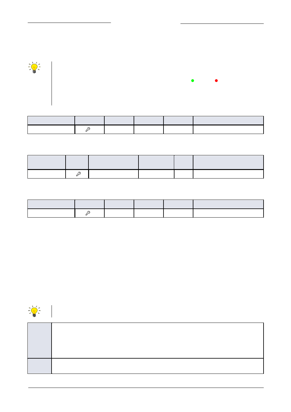
Change the baud rate, node address or parity of the side-connector RS485 (FLOW-BUS or Modbus) interface (if installed) with the
following parameters in the 'Configuration Mode'.
Note: an instrument with 9-pin sub-D side connector set for RS485 FLOW-BUS or Modbus communication will not
respond when connecting to an RS232 configuration. If the instrument is not set for RS232 communication, use the
micro switch on top of the instrument to overrule the custom settings and switch to RS232 communication settings:
press and hold the micro switch at power-up and wait (12…16 sec) until both green and red LEDs flash (0.2 sec
on, 0.2 sec off). Release the switch to activate the ‘Configuration Mode’. In the ‘Configuration Mode’ the bus type
and baud rate for the 9-pin sub-D side connector are set to RS232 FLOW-BUS (Propar) at 38400 Baud. The
‘Configuration Mode’ remains active after power down. Use the same procedure to deactivate the ‘Configuration
Mode’.
Fieldbus 2 address
Type
Access
Range
FlowDDE
FLOW-BUS
Modbus
Unsigned char
RW
0…255
309
124/10
0xFC50/64593
For the accepted values see the applicable field bus in chapter 3.
Fieldbus 2 baudrate
Type
Access
Range
FlowDDE
FLOW
-BUS
Modbus
Unsigned long
RW
0…10000000000
310
124/9
0xFC48...0xFC49/64585...64586
For the accepted values see the applicable field bus in chapter 3.
Fieldbus 2 parity
Type
Access
Range
FlowDDE
FLOW-BUS
Modbus
Unsigned char
RW
0…2
336
124/12
0xFC60/64609
The following values are accepted:
0 – no parity
1 – odd parity
2 – even parity
4.4
Special instrument features
4.4.1
Customized IO options (pin 5)
EL-FLOW Prestige instruments offer various customized input/output functions through pin 5 of the 9-pin sub-D side connector as
an option. A number of the (factory installed) programmable IO options are offered as standard, these options are described in this
section. The last three characters of the model key (presented on the back-side label of the instrument) indicate the installed IO
configuration, see also section 1.5. The standard options are described below (the default selection is …-A1V). Refer to document
9.16.118 for the applicable hook-up diagrams.
The customized IO options are factory installed, as indicated by last three characters of the model key (presented on
the back-side label of the instrument). These IO options cannot be changed manually.
A1V
0…10 Vdc output, controller (default selection)
Analog signal for pump or external valve steering (control signal only).
When the controller output is used for pump or external valve steering (Mass Flow Meters only), make sure the
‘
231
Valve Maximum’ is set to 0.3 [A]. For Mass Flow Controllers, the controller output is limited to a value below
10 Vdc due to the maximum valve current restriction.
B1V
4…20 mA output, controller
Analog signal for pump or external valve steering (control signal only).