Analog / digital operation, Analog / local operation, Digital rs232 operation – Bronkhorst EL-FLOW Prestige User Manual
Page 11: Digital rs485 / bus operation, Micro switch operation, 7 analog / digital operation, 8 micro switch operation
Bronkhorst High-Tech B.V.
EL-FLOW Prestige
11
9.17.084
2.7
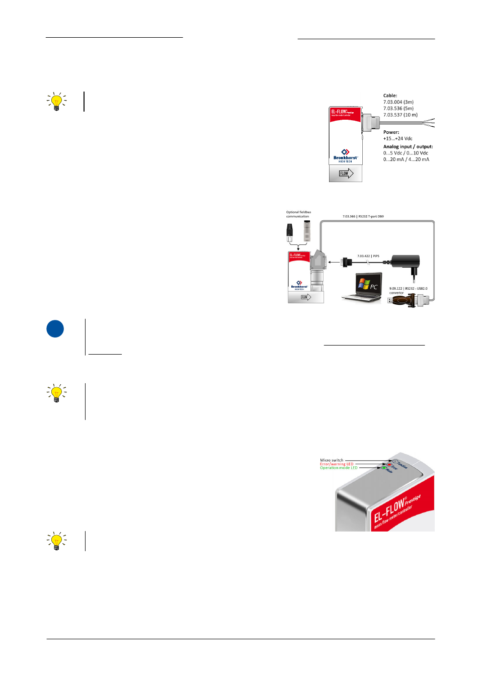
Analog / digital operation
2.7.1
Analog / local operation
Connect the EL-FLOW Prestige to the power supply/readout unit using
a cable with 9-pin sub-D connector
2.7.2
Digital RS232 operation
Digital operation over RS232 can be established when using the following
setup or using a Bronkhorst E-8000 readout/control unit. See section
3.4.1 for connecting to an E-8000. Connecting the instrument with an
RS232 cable or an RS232 cable with a USB to RS232 converter to a PC will
allow you to use (free) Bronkhorst software for Windows, such as
FlowDDE and FlowPlot. Make sure that the instrument back-side label
indicates RS232 settings for the 9-pin sub-D connector and apply the
proper baud rate settings. If the instrument is not set for RS232
communication, please refer to section 3.4 for switching to RS232
communication settings via the 'Configuration Mode'.
i
www
A PiPS (Plug-in Power Supply, art.nr.: 7.03.422) is available to power a single instrument and can be used instead of
the DB9 Loose-end cable as shown in the example above. Detailed information can be found in the manual PiPS
(9.17.055) which can be downloaded at the download section from the website: http://www.bronkhorst.com/en/
downloads
2.7.3
Digital RS485 / bus operation
With digital operation over RS485 or Ethernet a bus-system with multiple instruments can be set up. For RS485
FLOW-BUS or Modbus operation over the 9-pin sub-D connector or via an additional field bus driver (if installed), see
section 3.5. For operation via other additional field bus systems (e.g. DeviceNet
TM
, EtherCAT®), refer to section 3.6 or
the specific field bus manual.
2.8
Micro switch operation
Using the two colored LEDs and the micro switch on the EL-FLOW Prestige,
several actions can be monitored and started. The green LED is used for status
indication. The red LED is used for errors, warnings and messages. The switch
can be used to start several actions, such as auto-zero, restore factory settings
and bus-initialization actions, if applicable. See specific zero-procedure below
(section 2.9) for more details.
The micro switch on top of the EL-FLOW Prestige can be operated with a thin, metal or hard plastic pin. For example
the end of a paperclip.