Field bus operation, Flow-bus master/slave controller operation, Changing baud rate, node address and parity – Bronkhorst EL-FLOW Prestige User Manual
Page 42: 3 field bus operation, 1 flow-bus master/slave controller operation, 2 changing baud rate, node address and parity
Bronkhorst High-Tech B.V.
EL-FLOW Prestige
9.17.084
42
4.3
Field bus operation
4.3.1
FLOW-BUS master/slave controller operation
EL-FLOW Prestige instruments offer possibilities for master/slave control via FLOW-BUS. The output value of any instrument
connected to FLOW-BUS is automatically available to all other instruments (without extra wiring). To setup master/slave control the
‘
12
Control Mode’ of the instrument can be set to ‘FLOW-BUS Slave’ (value 2) or to ‘FLOW-BUS Analog Slave’ (value 13), depending
on how the ‘
139
Slave Factor’ should be set. Via the parameter ‘
158
Master Node’ the master device for the instrument is set. It is
possible to have multiple masters and slaves in a FLOW-BUS system. A slave instrument can also be a master for other instruments.
Setpoints from master instruments can be received via FLOW-BUS only. The parameters for master/slave control can
be changed through both RS232 and FLOW-BUS.
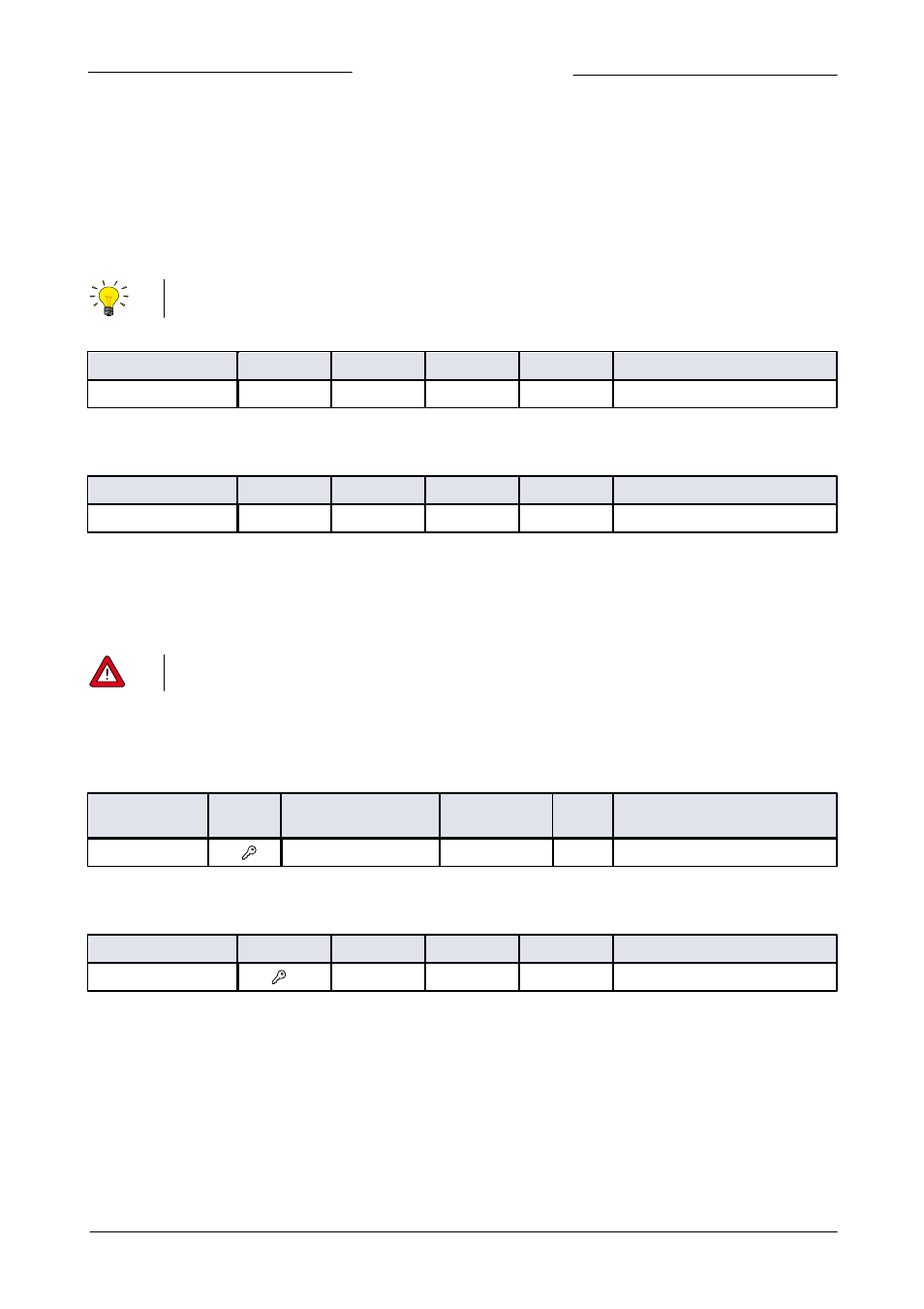
Master Node
Type
Access
Range
FlowDDE
FLOW-BUS
Modbus
Unsigned char
RW
1…125
158
33/14
0x042E/1071
Set the master node for the instrument.
Slave Factor
Type
Access
Range
FlowDDE
FLOW-BUS
Modbus
Float
RW
0…500
139
33/1
0x0421/1058
The controller output from the master instrument is multiplied by the ‘
139
Slave Factor’/100% to get the slave instrument setpoint.
Example: if a master output is 80% and the ‘
139
Slave Factor’ value = 50, then the slave instrument setpoint is 80% x 50%/100% =
40%.
4.3.2
Changing baud rate, node address and parity
Any changes made to the instrument communication settings will not be restored after a factory reset. See section
5.2 for more details.
Top connector communication
Change the node address of the instrument by using the instructions for the applicable field bus in chapter 3. Change the baud rate
or parity of the installed field bus (top connector) with the following parameters using the RS232 interface:
Fieldbus 1 baudrate
Type
Access
Range
FlowDDE
FLOW
-BUS
Modbus
Unsigned long
RW
0…10000000000
201
125/9
0xFD48...0xFD49/64841...64842
For the accepted values see the applicable field bus in chapter 3.
Fieldbus 1 parity
Type
Access
Range
FlowDDE
FLOW-BUS
Modbus
Unsigned char
RW
0…2
335
125/12
0x0FAC/4013
The following values are accepted:
0 – no parity
1 – odd parity
2 – even parity