Software, Baud rate, node address and parity setup, 2 software – Bronkhorst EL-FLOW Prestige User Manual
Page 22: 3 baud rate, node address and parity setup
Bronkhorst High-Tech B.V.
EL-FLOW Prestige
9.17.084
22
3.5.2
Software
When using a pc to communicate with EL-FLOW Prestige instruments only the FLOW-BUS protocol is supported by Bronkhorst
software. When using Modbus operation, software from third parties, such as LabVIEW, ModScan or a Modbus PLC must be used
to serve as Modbus master.
Note: an instrument with 9-pin sub-D side connector set for RS485 FLOW-BUS or Modbus communication will not
respond when connecting to an RS232 configuration. If the instrument is not set for RS232 communication, use the
micro switch on top of the instrument to overrule the custom settings and switch to RS232 communication settings:
press and hold the micro switch at power-up and wait (12…16 sec) until both green and red LEDs flash (0.2 sec
on, 0.2 sec off). Release the switch to activate the ‘Configuration Mode’. In the ‘Configuration Mode’ the bus type
and baud rate for the 9-pin sub-D side connector are set to RS232 FLOW-BUS (Propar) at 38400 Baud. The
‘Configuration Mode’ remains active after power down. Use the same procedure to deactivate the ‘Configuration
Mode’.
3.5.3
Baud rate, node address and parity setup
EL-FLOW Prestige instruments are configured from factory as indicated on the instrument back-side label. If there is a need of
changing any of the specified RS485 settings, see the tables below for the supported configurations. The default selections are
presented in bold.
Mode:
Digital
Interface/medium:
RS485
Protocol:
FLOW-BUS
Modbus RTU
Modbus ASCII
Baud rate:
187500
400000
9600
19200
38400
56000
57600
115200
128000
256000
9600
19200
38400
56000
57600
115200
128000
256000
Node address:
3…125
1…247
1…247
Parity:
None
None; Even; Odd
None; Even; Odd
RS485 FLOW-BUS/Modbus communication options
Changing RS485 settings of the RJ-45 top connector interface
In case the FLOW-BUS or Modbus RJ-45 field bus connector is used for bus communication,
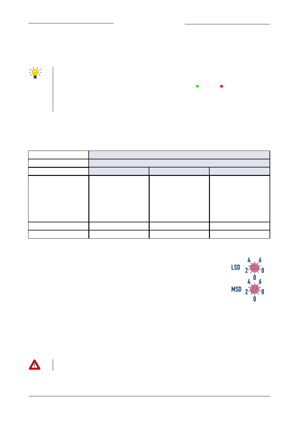
the node address can be easily set by using the rotary switches on the side of the
instrument. Use the ‘MSD’ (Most Significant Digit) to set the ‘tens’ of the bus-address and
the ‘LSD’ (least Significant Digit) to set the ‘unit’ of the bus-address (the example on the right
reads ‘63’). Set the rotary switches to '00' for automatic installation. Refer to the
corresponding field bus manual, document 9.17.024 (FLOW-BUS) or document 9.17.035
(Modbus) for more details.
For changing the baud rate or parity settings use the RS232 interface to change the
corresponding parameters (see section 4.3.2).
Changing RS485 settings of the 9-pin sub-D side connector interface
In case the 9-pin sub-D side connector is set for RS485 communication, the baud rate or node address can be changed by using the
micro switch or by changing the settings in the ‘Configuration Mode’. Refer to section 3.8 for changing node address and baud rate
with the micro switch. Other communication parameters can be changed only in the ‘Configuration Mode’. Activate the
‘Configuration Mode’ by pressing the micro switch at start-up according the description in section 3.5.2 above. In ‘Configuration
Mode’ the bus type and baud rate are set to RS232 FLOW-BUS (Propar) at 38400 Baud. Change the appropriate parameters as
described in section 4.3.2. When finished, deactivate the ‘Configuration Mode’ using the same procedure. Now the instrument is
ready to use in the desired configuration with the adjusted baud rate, node address or parity.
Any changes made to the instrument communication settings will not be restored after a factory reset. See section
5.2 for more details.