Howtorfid – Avery Dennison RFID User Manual
Page 12
HowToRFID
Revision: 13
Date: 31 August 2009
Page 12 of 53
Printer
PH-CT [mm]
PH-TB [mm]
PH-CA [mm]
PH-DE [mm]
MBF [mm]
64-0X
17.13
10.50
62.00
48.50
AP 5.4
17.00
10.00
46.50
16
ALX 92x / DPM
n/a
n/a
50.00
24.20 (short
dispensing
edge)
39.80 (long
dispensing
edge)
ca. 100
Table 3 –Paper path dimensions of printer relevant for RFID
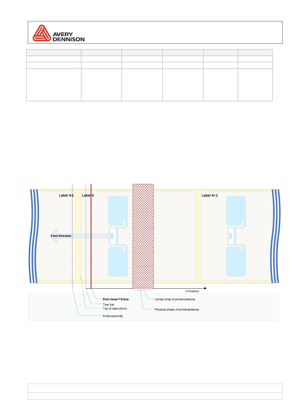
2.4.3
Inlay position / Tag antenna coupling
Smart labels with RFID functionality are treated by the printer in a
two phase process. At first RFID functionality is
executed and afterwards the regular print processing is made. To communicate with an RFID transponder it has to
be in the range (RF field) of the built in reader antenna and it must be the only tag in range. For this purpose the
Easy Plug command #IM has been extended with a parameter called
RFID antenna offset. It defines the distance
between label start and optimal coupling point position. In other words, it determines how much the label needs to
be back feed to bring the transponder in the right position near the printer’s antenna.
Figure 2: positioning at label start
- Monarch 1730 (4 pages)
- Pathfinder 6032 Supply (1 page)
- Pathfinder 6032 Quick Start (12 pages)
- Pathfinder 6032 Wrist Strap (4 pages)
- Platinum 6039 System Administrator Guide (48 pages)
- Platinum 6039 Weights and Measures (2 pages)
- Pathfinder 6140 Equipment Manual (36 pages)
- Pathfinder 6057 Quick Reference (40 pages)
- Pathfinder 6057 Quick Reference (115 pages)
- Pathfinder 6057 System Administrator Guide (60 pages)
- Pathfinder 6140 LNT Programmer Manual using XML (80 pages)
- Pathfinder 6140 Quick Reference (30 pages)
- FreshMarx 9415 Operator Handbook (44 pages)
- FreshMarx 9415 Maintenance Instructions (2 pages)
- FreshMarx 9415 System Administrator Guide (48 pages)
- Monarch 9416 XL Printer Equipment Manual (30 pages)
- Monarch 9416 XL Quick Reference (22 pages)
- FreshMarx 9415 Quick Reference (48 pages)
- Monarch 9416 XL AAFES Setup (4 pages)
- Monarch 9855 XL Intelligent Kit (34 pages)
- FreshMarx 9417 Replacing the Printhead (4 pages)
- FreshMarx 9417 Quick Reference (10 pages)
- Sierra Sport4 9493 Packet Reference Manual (230 pages)
- FreshMarx 9417 Operator Handbook (28 pages)
- Sierra Sport3 9433 Quick Reference (6 pages)
- FreshMarx 9417 System Administrator Guide (70 pages)
- 9450 RASCAL Programmer Manual (84 pages)
- Sierra Sport4 9493 System Administrator Guide (32 pages)
- Sierra Sport4 9493 Quick Reference (8 pages)
- Monarch 9855 RFMP Quick Reference (18 pages)
- 9850 Operator Handbook (134 pages)
- 7410 Network Card Programmer Manual (78 pages)
- Monarch 9855 MLI (4 pages)
- Monarch 9860 Quick Reference (12 pages)
- Monarch 9860 Operator Handbook (118 pages)
- Monarch 9860 Programmer Manual Addendum2 (14 pages)
- Monarch 9860 Programmer Manual Addendum (8 pages)
- Monarch 9864 Advanced Applications (21 pages)
- Monarch 9864 Quick Reference (28 pages)
- Monarch 9864 Error Messages (67 pages)
- Monarch 9864 Bar Code Information (19 pages)
- Monarch 9864 Command Overview (26 pages)
- Monarch 9878 (24 pages)
- Monarch 9864 Info Printouts and Parameters (111 pages)
- Monarch 9906 Quick Reference (48 pages)