Making j2 connections – AMETEK XHR 1000 Watt Series User Manual
Page 21
Features and Specifications
Rear Panel Connectors and Switch
21
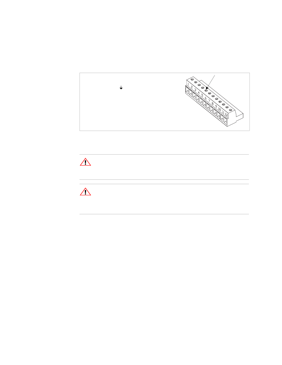
See Figure 1.5 to identify the function of each of the 12 terminals on the J2
connector.
Figure 1.5 J2 Programming Connector
Making J2 Connections
Make connections to the J2 connector using its screw-type wire clamps. Before
making any connections, turn the power supply OFF and wait until the front panel
displays have gone out. You can unplug the connector from the back of the unit in
order to make it easier to install the required wiring.
!
CAUTION
To maintain the isolation of the power supply output and prevent ground loops,
use an isolated (ungrounded) programming source when operating the power
supply via remote analog control at the J2 connector.
!
CAUTION
Do not attempt to bias the Program/monitor signal return (J2-6) relative to the
power supply output return, as they are connected internally. Use the Isolated
Programming (ISOL) option for control from programming sources at potentials
differing from the supply output return.
Wire Clamp
Connector Screw
1
Return Sense (–SNS)
2
Positive Sense (+SNS)
3
Control Ground (
)
4
Remote Output Voltage Programming Select (VRMT)
5
Remote Current Limit Programming Select (IRMT)
6
Program/Monitor Signal Return (PGM–)
7
Output Voltage Programming Input (VPGM)
8
Output Current Limit Programming Input (IPGM)
9
Output Voltage Monitor (VMON)
10 Output Current Monitor (IMON)
11 Shutdown Input (S/D+)
12 Shutdown Signal Return (S/D–)