150 v to 600 v models, 150 v to 600 v models –17, Figure 2-6 – AMETEK XFR 2800 Watt Series User Manual
Page 45: Warning: shock hazard
Load Connection
TM-F2OP-C1XN-01
2-17
150 V to 600 V Models
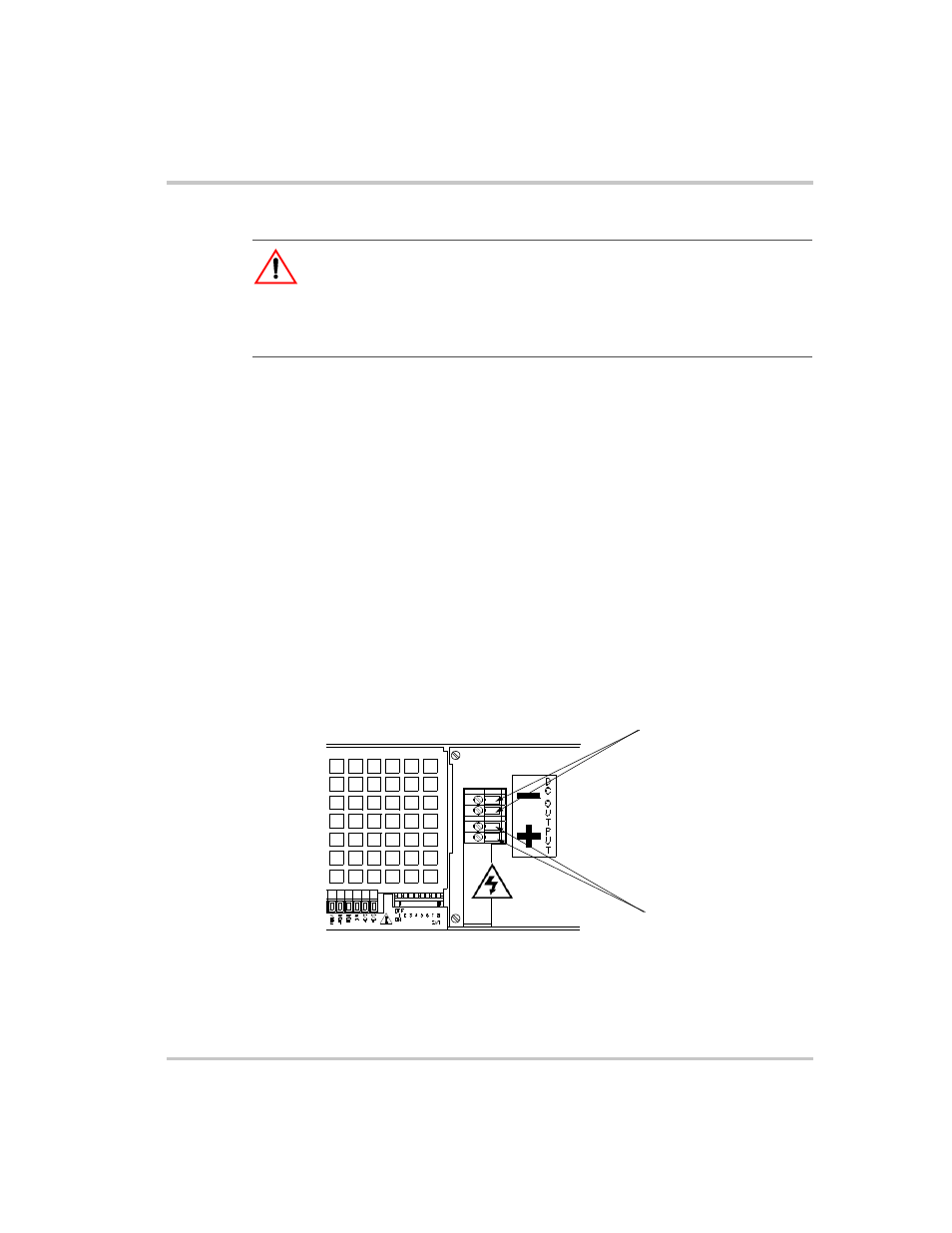
The 150 V to 600 V models have a 4-terminal, wire clamp output
connector. See Figure 2-6 for a labelled drawing of the wire clamp
connector. To prepare and connect the load wiring:
1. Strip 0.4 in. (10 mm) at the ends of the wires.
2. Remove the top part of the output cover. Do not remove the
chassis-mounted part of the cover.
3. Loosen wire clamp screws (part of strain relief). Do not disassemble
the strain relief.
4. Insert load wire in strain relief.
5. To connect the wiring, loosen each terminal screw, insert a stripped
wire into the terminal, and tighten the screw securely.
6. Tighten the strain relief clamp.
7. Replace the top cover.
WARNING: Shock hazard
To protect personnel against accidental contact with hazardous voltages, ensure
that the load, including connections, has no live parts which are accessible. Also
ensure that the insulation rating of the load wiring and circuitry is greater than or
equal to the maximum output voltage of the power supply.
Figure 2-6 Output Voltage Connector
(For 150 V to 600 V models.)
Negative Output/Return (–)
Positive Output (+)