Figure 1-1, Power supply front panel –4, See figure 1-1 to review the controls – AMETEK XFR 2800 Watt Series User Manual
Page 22
Features and Specifications
1-4
TM-F2OP-C1XN-01
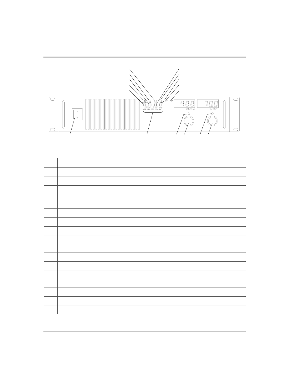
Figure 1-1 Power Supply Front Panel
No.
Description
1
OVP Check: OVP Setting Preview Switch (See page 3–7 for more information.)
2
OVP Set: OVP Adjust Potentiometer (See page 3–7 for more information.)
3
V/I Check: Local Voltage & Current Limit Setting Preview Switch (See page 2–9 for more
information.)
4
OVP Shutdown LED
5
S/D: Shutdown LED
6
Standby Switch (See page 3–9 for more information.
7
Rem: Remote Programming LED
8
Local: Return to Local Programming, for units with digital programming interface installed
9
OTP: Over Temperature Shutdown LED
10
ACF: AC Fail LED
11
AC Power Switch
12
Remote Programming LEDs: For units with digital programming interface installed
13
Voltage Mode LED
14
Output Voltage Control Knob
15
Current Mode LED
16
Output Current Control Knob
11
12
13
14
16
15
8
1
6
7
9
10
3
5
4
2
- CW-M (48 pages)
- CW-M Corrected Table 4-2 in (1 page)
- CW-P (62 pages)
- Lx Series (205 pages)
- CW Series Programming Manual (25 pages)
- Ls Series II Programming Manual (242 pages)
- Compact i/iX Series (157 pages)
- Compact IX 2253 (157 pages)
- Compact i/iX Series Software Manual (203 pages)
- ASD Series Quick Start (5 pages)
- ASD Series (120 pages)
- i-iX Series II Programming Manual (226 pages)
- DLM 600W Series Programming Manual (24 pages)
- M131 Programming Manual (99 pages)
- DLM Series (74 pages)
- DLM 600W Series (82 pages)
- BPS Series (153 pages)
- DLM600 Series (16 pages)
- DCS-E 1.2kW Series (65 pages)
- DLM-E 4kW Series Programming Manual (32 pages)
- M136 (8 pages)
- DCS-E 3kW Series (94 pages)
- CTS 3.0 (166 pages)
- CSW Series (174 pages)
- 2003RP (126 pages)
- 2001RP (131 pages)
- MX CTSH (151 pages)
- MXCTSL Administrator Manual (27 pages)
- MX CTSL (157 pages)
- RS Series (228 pages)
- MX Series Installation Manual (35 pages)
- Ls AC source (2 pages)
- MX15 Series (184 pages)
- Ls Series II (226 pages)
- Lx Series Driver Manual (275 pages)
- MX Series Rev: AY (257 pages)
- iX Series (341 pages)
- i-iX Series II (258 pages)
- GUPS 2400A-108 (36 pages)
- HPD Series (58 pages)
- HPD Series Operation Manual (41 pages)
- HPD Series GPIB-Multichannel (134 pages)
- PLA-PLW Programming Manual (74 pages)
- ReFlex Mating Connnectors for Controller (3 pages)
- LPDC-16V (4 pages)