5 v to 100 v models, 5 v to 100 v models –16, Figure 2-5 – AMETEK XFR 2800 Watt Series User Manual
Page 44
Installation
2-16
TM-F2OP-C1XN-01
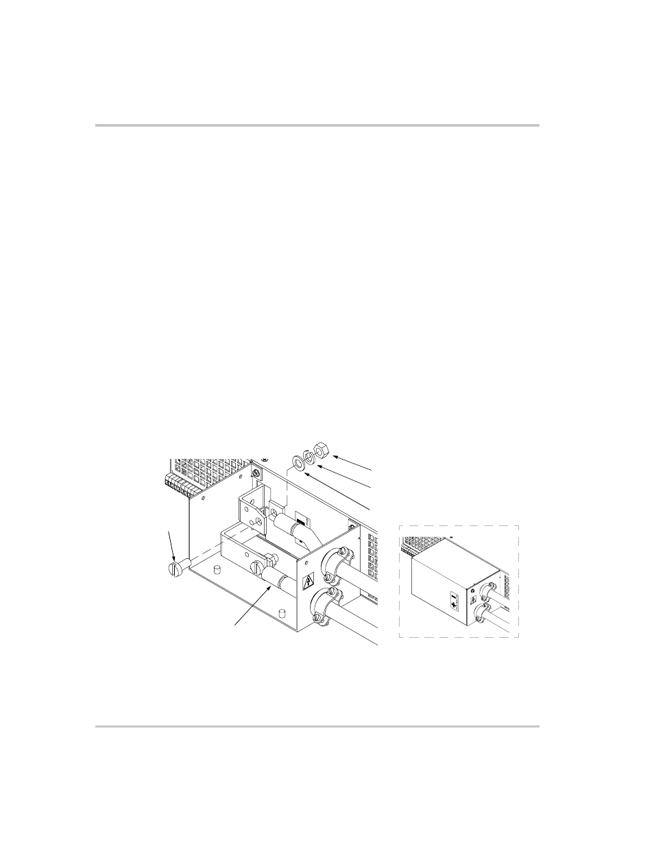
7.5 V to 100 V Models
The 7.5 V to 100 V models are equipped with output bus bars. To make a
typical load connection to a 7.5 V, 300 A power supply:
1. Strip the ends of the wires.
2. Remove the top part of the output cover. Do not remove the
chassis-mounted part of the cover.
3. Loosen wire clamp screws (part of strain relief). Do not disassemble
the strain relief.
4. Insert load wire in strain relief.
5. Install connectors to load wiring.
6. Fasten connectors to bus bars with 5/16 in. x 5/8 in. (M8 x 16 mm)
screws, 5/16 in. (M8) flat washers, lock washers, and hex nuts as
shown in Figure 2-5.
7. Tighten the strain relief clamp.
8. Replace the top cover.
Note:Bus bar hole sizes are one of 0.343 in. (8.7 mm) D; two of 0.197 in.
(5.0 mm) D.
Figure 2-5 Typical Load Connection Hardware
(For 7.5 V to 100 V models)
Hex Nut (2 places)
Lock Washer (2 places)
Flat Washer (2 places)
Screw (2 places)
Wire connector (2 places)
Assembled View
- CW-M (48 pages)
- CW-M Corrected Table 4-2 in (1 page)
- CW-P (62 pages)
- Lx Series (205 pages)
- CW Series Programming Manual (25 pages)
- Ls Series II Programming Manual (242 pages)
- Compact i/iX Series (157 pages)
- Compact IX 2253 (157 pages)
- Compact i/iX Series Software Manual (203 pages)
- ASD Series Quick Start (5 pages)
- ASD Series (120 pages)
- i-iX Series II Programming Manual (226 pages)
- DLM 600W Series Programming Manual (24 pages)
- M131 Programming Manual (99 pages)
- DLM Series (74 pages)
- DLM 600W Series (82 pages)
- BPS Series (153 pages)
- DLM600 Series (16 pages)
- DCS-E 1.2kW Series (65 pages)
- DLM-E 4kW Series Programming Manual (32 pages)
- M136 (8 pages)
- DCS-E 3kW Series (94 pages)
- CTS 3.0 (166 pages)
- CSW Series (174 pages)
- 2003RP (126 pages)
- 2001RP (131 pages)
- MX CTSH (151 pages)
- MXCTSL Administrator Manual (27 pages)
- MX CTSL (157 pages)
- RS Series (228 pages)
- MX Series Installation Manual (35 pages)
- Ls AC source (2 pages)
- MX15 Series (184 pages)
- Ls Series II (226 pages)
- Lx Series Driver Manual (275 pages)
- MX Series Rev: AY (257 pages)
- iX Series (341 pages)
- i-iX Series II (258 pages)
- GUPS 2400A-108 (36 pages)
- HPD Series (58 pages)
- HPD Series Operation Manual (41 pages)
- HPD Series GPIB-Multichannel (134 pages)
- PLA-PLW Programming Manual (74 pages)
- ReFlex Mating Connnectors for Controller (3 pages)
- LPDC-16V (4 pages)